Directional electromagnetic measurements insensitive to dip and anisotropy

a technology of anisotropy and directional electromagnetic measurement, applied in the field of well logging, can solve the problems of forming anisotropy on the resulting measurements, the operator of the well, and the general inability of the instruments to resolve the azimuthal variation in the conductivity of the formation surrounding the instrument,

Inactive Publication Date: 2005-11-29
SCHLUMBERGER TECH CORP
View PDF18 Cites 118 Cited by
  • Summary
  • Abstract
  • Description
  • Claims
  • Application Information

AI Technical Summary

Problems solved by technology

However, this is often not the situation.
Layering of the formations, however, may be such that the pay zone does not lie along a predictable trajectory at geographic positions distant from the surface location of the wellbore.
This presents a problem to the wellbore operator, who must correct the wellbore trajectory to maintain the selected position in the pay zone.
However, conventional propagation-type instruments are capable of resolving axial and lateral (radial) variations in conductivity of the formations surrounding the instrument, but the response of these instruments generally cannot resolve azimuthal variations in the conductivity of the formations surrounding the instrument.
Disadvantages of these techniques include the coupled effects of dip and formation anisotropy on the resulting measurements.

Method used


Image

  • Directional electromagnetic measurements insensitive to dip and anisotropy
  • Directional electromagnetic measurements insensitive to dip and anisotropy
  • Directional electromagnetic measurements insensitive to dip and anisotropy

Examples


Embodiment Construction

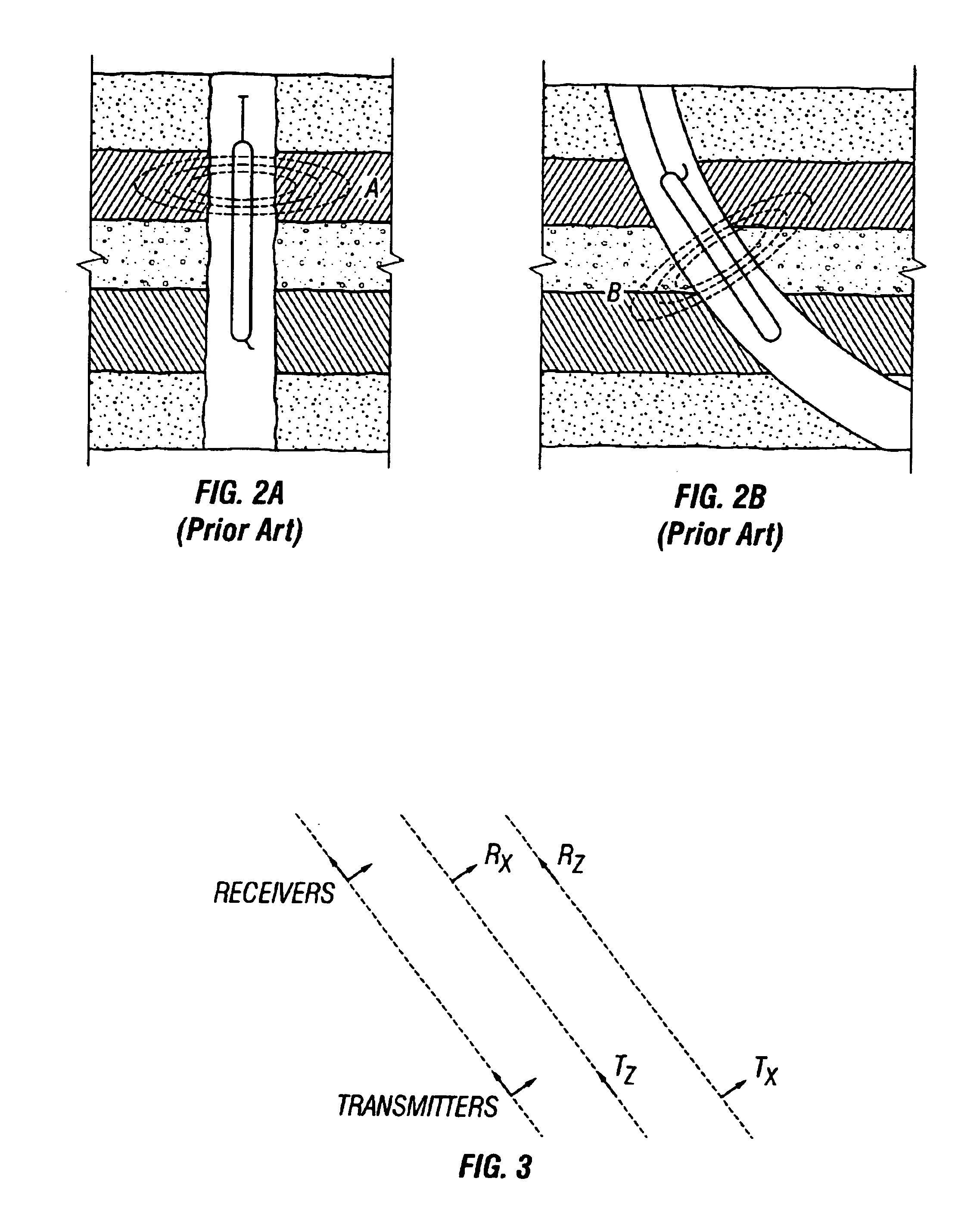
[0035]FIG. 3 illustrates a measurement technique according to the invention. The transmitters and receivers are approximated as point magnetic dipoles. The antennas labeled Z have a dipole moment along the tool axis; the antennas labeled X have a dipole moment perpendicular to the tool axis. The instrument does not move during this idealized measurement, but is displaced sideways in the FIG. 3 for clarity. In the interest of clarity, the instrument axis is generally represented as a dashed line. The Z transmitter is activated, and the voltage measured on the X receiver is denoted VZX. The X transmitter is then activated, and the voltage measured on the Z receiver is denoted VXZ. The cross-dipole measurement based on the difference VZX−VXZ is used to obtain information about adjacent bed boundaries. The mathematical theory underlying the invention is now presented.

[0036]Basic properties of the cross-dipole measurement. For a transmitter carrying a current I, the voltage V measured at...


PUM


Abstract

Systems and methods are provided for directional propagation-type logging measurements not sensitive to dip and anisotropy over a wide frequency range. Estimates of the distance of the logging tool to a bed boundary are obtained using “up-down” measurements with antenna configurations having tilted magnetic dipoles. These estimates are insensitive to anistropy and dip, undesirable complications of directional measurements.

Description

CROSS-REFERENCE TO RELATED APPLICATIONS[0001]This invention claims priority from U.S. Provisional Application Ser. No. 60 / 325,272 filed on Sep. 26, 2001 and U.S. Provisional Application Ser. No. 60 / 325,273 filed on Sep. 26, 2001.BACKGROUND OF INVENTION[0002]1. Field of the Invention[0003]The invention relates generally to the field of well logging. More particularly, the invention relates to improved techniques in which instruments equipped with antenna systems having transverse or tilted magnetic dipoles are used for improved electromagnetic measurements of subsurface formations.[0004]2. Background Art[0005]Various well logging techniques are known in the field of hydrocarbon exploration and production. These techniques typically use instruments or tools equipped with sources adapted to emit energy into a subsurface formation that has been penetrated by a borehole. In this description, “instrument” and “tool” will be used interchangeably to indicate, for example, an electromagnetic...

Claims


Application Information

Patent Timeline
Patent Type & Authority Patents(United States)
IPC IPC(8): G01V3/28
CPCG01V3/28
Inventor MINERBO, GERALD N.OMERAGIC, DZEVATROSTHAL, RICHARD A.
Owner SCHLUMBERGER TECH CORP
Why Eureka
Try Eureka