Integral lash adjustor for hydraulic compression engine brake

a technology of hydraulic compression engine and adjustor, which is applied in the direction of machines/engines, non-mechanical valves, output power, etc., can solve the problems of inability to adjust the lash, excessive noise, and limited flexibility of the exhaust valve opening, so as to prevent rotation

Inactive Publication Date: 2005-12-06
CATERPILLAR INC
View PDF14 Cites 2 Cited by
  • Summary
  • Abstract
  • Description
  • Claims
  • Application Information

AI Technical Summary

Problems solved by technology

Many of these retarders are mechanical in nature, and thus limited in their flexibility for exhaust valve opening due to the fixed structure of the engine brake.
The lack of flexibility produces fixed openings of the exhaust valve during the engine cycle, which creates excessive noise.
The placement of an adjusting screw for manually adjusting the lash between the engine brake system and the exhaust valve in the prior art has limited access of the adjusting screw, making attempts to adjust the lash cumbersome, cramped and therefore excessively difficult.

Method used


Image

  • Integral lash adjustor for hydraulic compression engine brake
  • Integral lash adjustor for hydraulic compression engine brake
  • Integral lash adjustor for hydraulic compression engine brake

Examples


Embodiment Construction

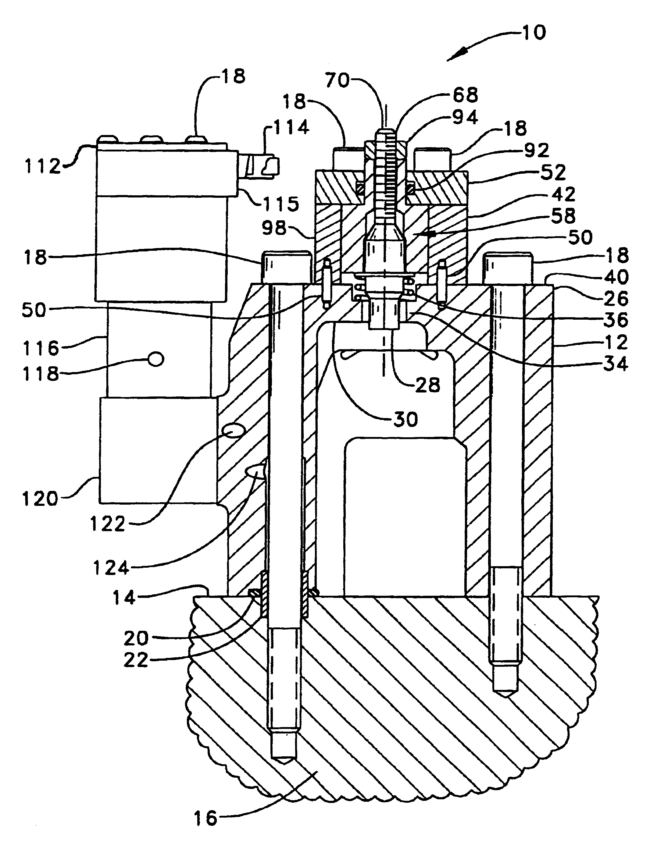
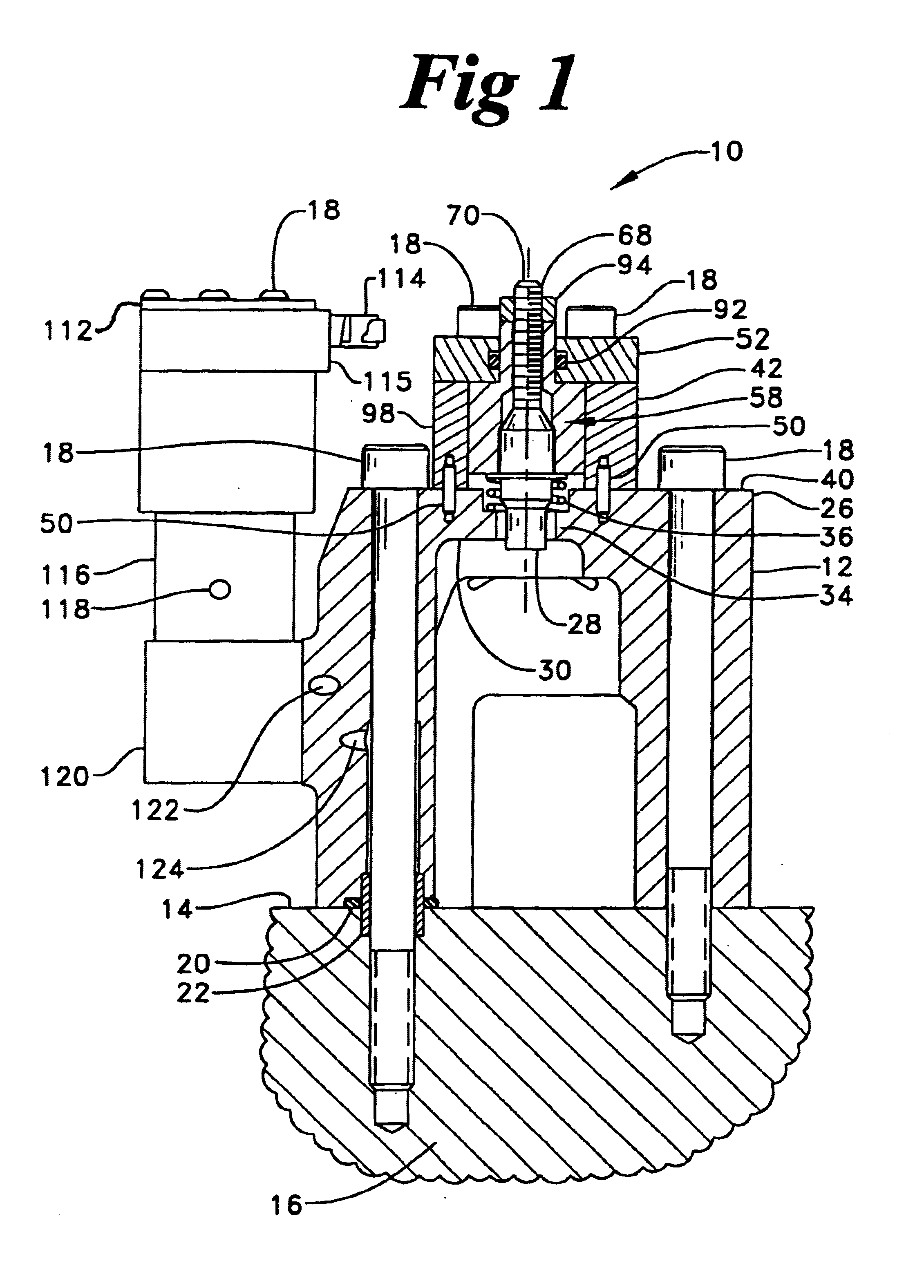
[0018]Referring now to FIGS. 1 through 5, and in particular to FIG. 1, an integral lash adjustor 10 for an engine brake 1 is shown. The integral lash adjustor 10 includes an engine brake stand 12 secured to a top side 14 of an engine block 16. The engine brake stand 12 is secured by at least one mechanical fastener 18. A nut / bolt assembly, locking nut / bolt assembly, or other fastener arrangement may be used as the mechanical fastener 18, as is common in the art depending on the requirements of the application. Surrounding the mechanical fastener 18 is an O-ring seal 20 and a hollow dowel 22 for locating the brake 1 relative to the engine block 16, in addition to providing a flow passage (not specifically shown) to an electronic valve assembly 110. The engine brake stand 12 is mounted to at least one engine cylinder (not shown).

[0019]The engine brake stand 12 has a top end 26 with an opening 28 therein for communication with an upper surface 30 of an engine brake cavity 32. The openi...


PUM


Abstract

Engine compression release brakes include some degree of lash between the brake actuation portion and the engine exhaust valve portion. The disclosed apparatus and method provides an integral lash adjuster that includes an adjusting screw that is threadably received by a slidable plunger. Rotation of the adjusting screw causes the plunger to slide relative to a plunger cavity and responsively modify the amount of lash.

Description

TECHNICAL FIELD[0001]The present invention relates generally to a hydraulic compression engine brake, and more particularly to an integral lash adjustor.BACKGROUND ART[0002]For many years it has been recognized that vehicles, and particularly trucks, equipped with internal combustion engines of the Otto or Diesel type should be provided with some form of engine retarder in addition to the usual wheel brake. The reason for this is the momentum of a heavily loaded vehicle descending a long grade may easily overcome the capacity for continuous braking of the wheel braking system. Many of these retarders are mechanical in nature, and thus limited in their flexibility for exhaust valve opening due to the fixed structure of the engine brake. The lack of flexibility produces fixed openings of the exhaust valve during the engine cycle, which creates excessive noise.[0003]Compression release engine brakes are well known as shown, for example, by U.S. Pat. No. 5,186,141, issued on Feb. 16, 19...

Claims


Application Information

Patent Timeline
Patent Type & Authority Patents(United States)
IPC IPC(8): F01L9/10F01L13/06
CPCF01L9/02F01L13/065F01L2760/004F01L2800/00F01L9/10
Inventor FUNKE, STEVEN J.HARMON, MICHAEL P.LEMAN, SCOTT A.MICKIEWICZ, MATTHEW G.
Owner CATERPILLAR INC
Why Eureka
Try Eureka