Simplified truck mounted brake system

Active Publication Date: 2005-12-06
WABTEC HLDG CORP +1
View PDF2 Cites 19 Cited by
  • Summary
  • Abstract
  • Description
  • Claims
  • Application Information

AI Technical Summary

Benefits of technology

[0011]Still yet another object of the present invention is to provide a simplified truck mounted brake system which requires less brake pipe per car.
[0012]A further object of the present invention is to provide a simplified truck mounted brake system which will reduce fuel consumption and/or enable a heavier payload to be carried by the rail car.
[0013]An additional object of the present invention is to provide a simplified truck mounted brake system which is less costly to produce than car mounted railway br

Problems solved by technology

However, each of these known brake systems have various drawbacks which are known in the railway braking art.
For example, car mounted type brake systems require several levers and linkages which are subject to frictional wear and other damage due to in track service thereby adding to costs from both an equipment investment and maintenance cost.
Furthermore, these car mounted brake systems add considerable weight to th

Method used


Image

  • Simplified truck mounted brake system
  • Simplified truck mounted brake system
  • Simplified truck mounted brake system

Examples


Embodiment Construction

, particularly, when such description is taken in conjunction with the attached drawing figures and with the appended claims.

BRIEF DESCRIPTION OF THE DRAWINGS

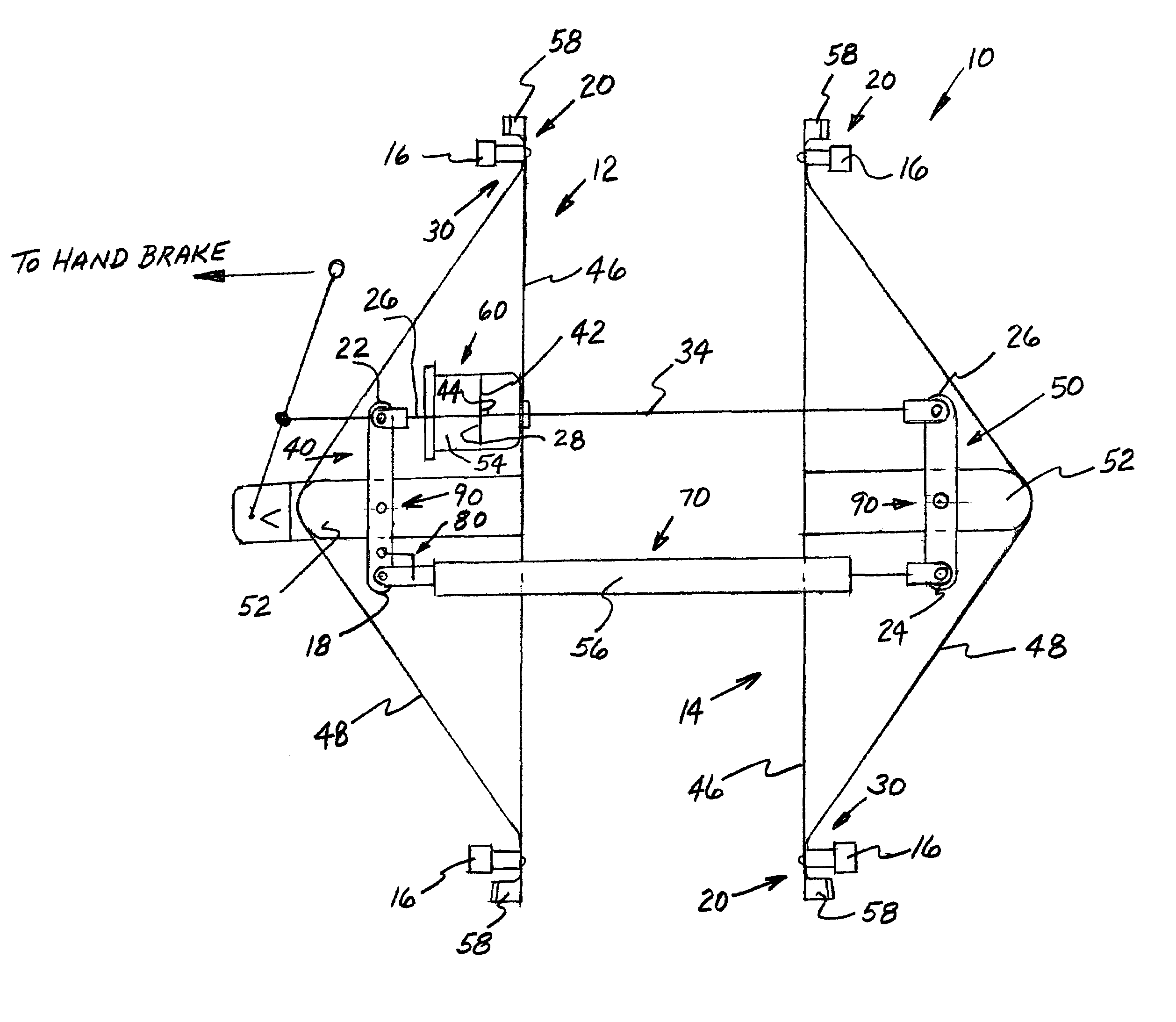
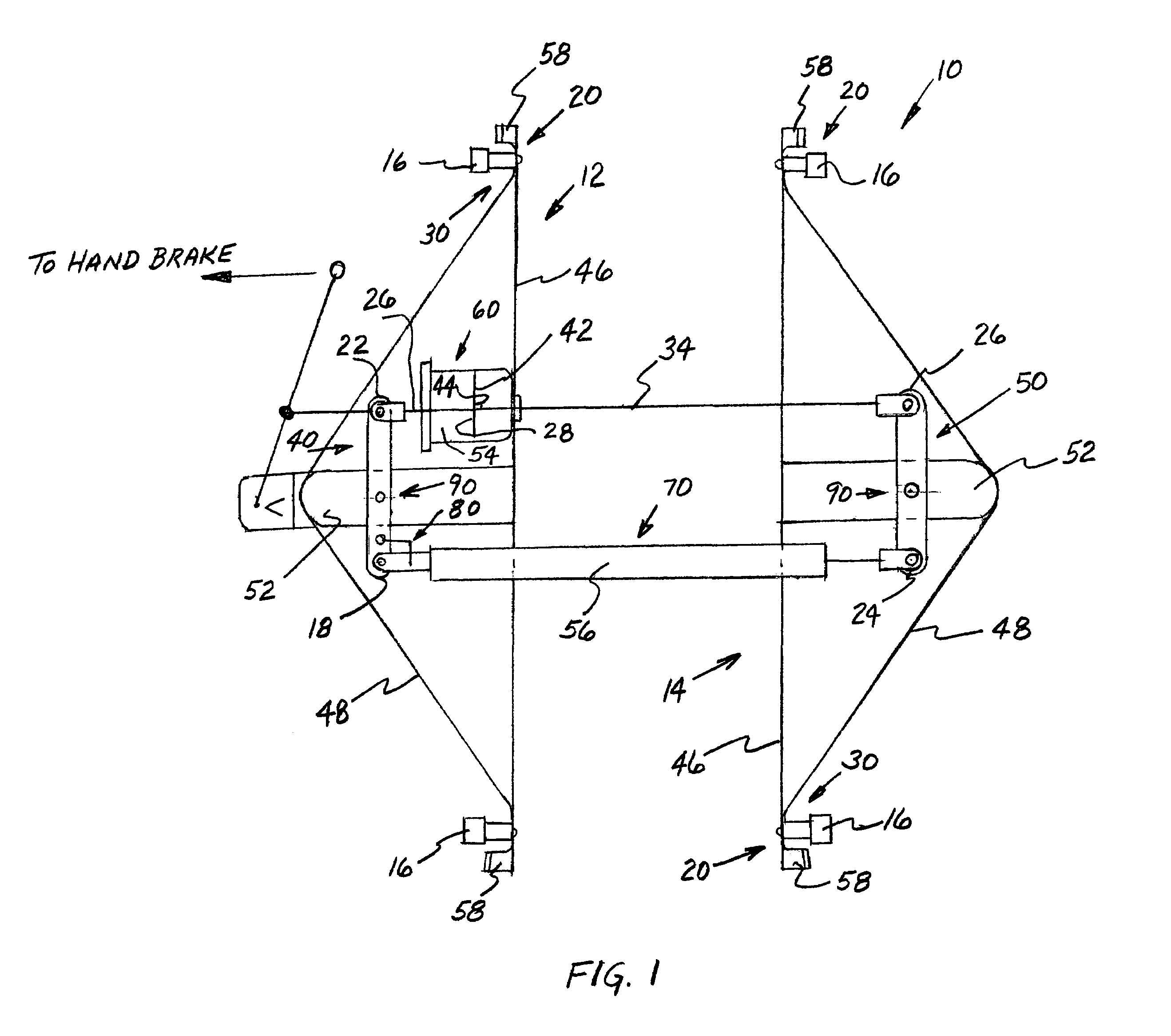
[0018]FIG. 1 is a schematic illustration of one embodiment of a truck mounted brake assembly according to the present invention;

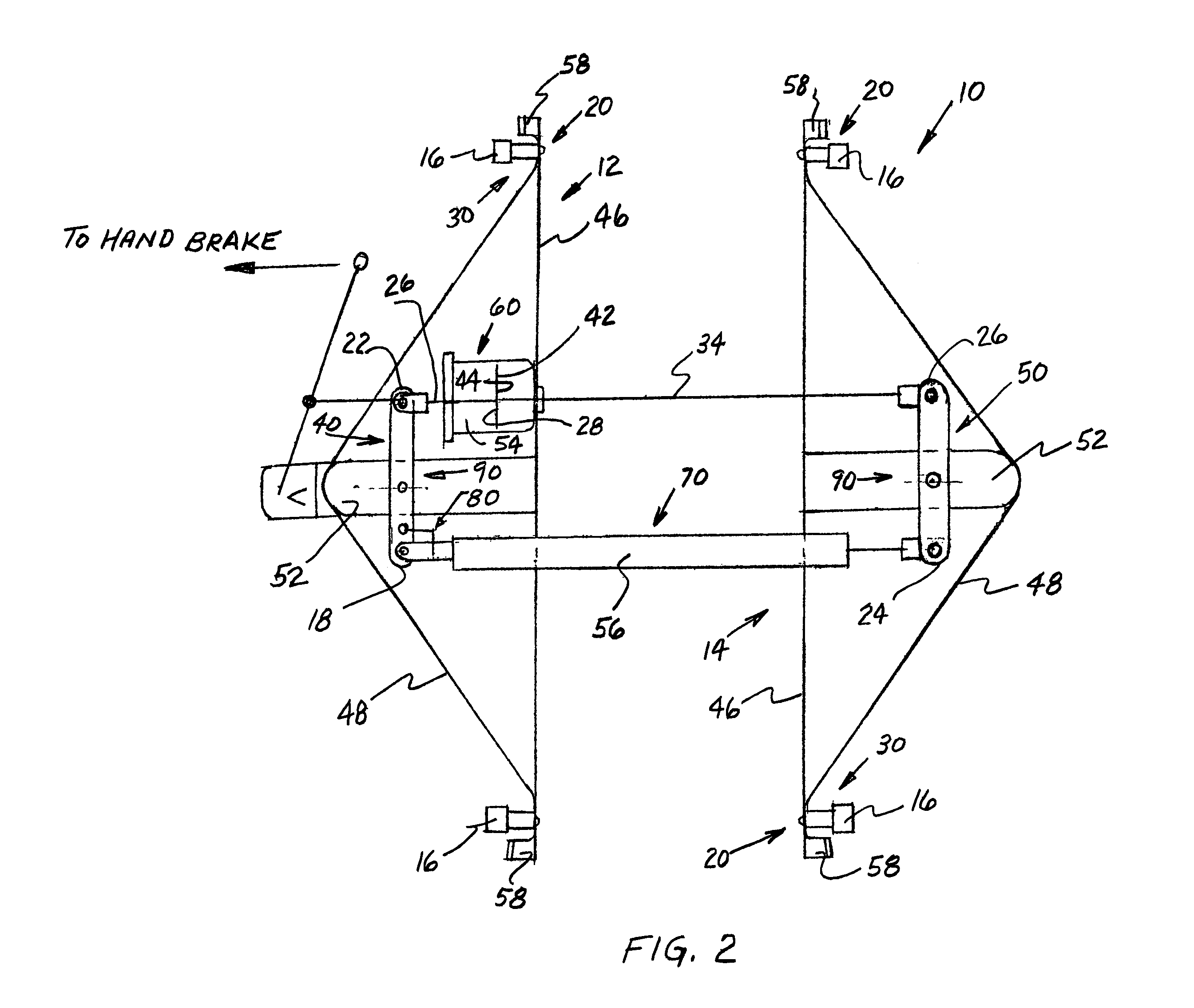
[0019]FIG. 2 is a schematic illustration of one alternative embodiment of a truck mounted brake assembly according to the present invention; and

[0020]FIG. 3 is a schematic illustration of another alternative embodiment of a truck mounted brake assembly according to the present invention.

BRIEF DESCRIPTION OF A PRESENTLY PREFERRED AND VARIOUS ALTERNATIVE EMBODIMENTS OF THE INVENTION

[0021]Prior to proceeding to the more detailed description of the instant invention it should be noted that, for the sake of clarity and understanding of the invention, identical components which have identical functions have been identified with identical reference numerals throughout the several views which have been illustr...


PUM


Abstract

A brake rigging comprising first and second brake beams. A brake shoe assembly including a brake shoe adjacent each end of brake beams. A first force transfer mechanism connected intermediate first and second ends thereof to the first brake beam for moving a brake shoe into engagement with confronting wheels during braking. A second force transfer mechanism connected intermediate first and second ends thereof for moving brake shoes into engagement with confronting wheels during braking. A first force transmitting device engageable with such second brake beam for rotating such second force transfer mechanism. An adjustable length second force transmitting device having one end connected to the first force transfer mechanism and another end connected to the second force transfer mechanism and an apparatus engageable with such second force transmitting device and a portion of such brake rigging for changing a length of the second force transmitting device.

Description

FIELD OF THE INVENTION[0001]The present invention relates, in general, to railway vehicle brake systems such as are used on freight cars and, more particularly, this invention relates to a simplified truck mounted brake system for use on a railway vehicle and which can be readily adapted to retrofit onto existing railway vehicles.BACKGROUND OF THE INVENTION[0002]Prior to the conception and development of the present invention, numerous types of brake systems were known and used on railway cars. These prior art type brake systems include car mounted systems as well as truck mounted systems. However, each of these known brake systems have various drawbacks which are known in the railway braking art.[0003]For example, car mounted type brake systems require several levers and linkages which are subject to frictional wear and other damage due to in track service thereby adding to costs from both an equipment investment and maintenance cost. Furthermore, these car mounted brake systems ad...

Claims


Application Information

Patent Timeline
IPC IPC(8): B60T11/10B61H13/00B61H13/24B61H13/36
CPCB61H13/24B61H13/36B61H11/06B61H13/20B61H13/28
Inventor RING, MICHAEL E.ZEMYAN, JAMES M.
Owner WABTEC HLDG CORP
Why Eureka
Try Eureka