Luminaire globes having internal light control elements

a technology of light control elements and luminaire globes, which is applied in outdoor lighting, fixed installation, lighting and heating apparatus, etc., can solve the problems of limiting beam intensity at certain angles, and merritt does not provide a secondary reflective structure or light control structure within the interior of the disclosed luminaire globes, so as to maximize the desired illumination level, desired cutoff characteristics, and desired cutoff characteristics

Inactive Publication Date: 2005-12-06
ABL IP HLDG
View PDF10 Cites 24 Cited by
  • Summary
  • Abstract
  • Description
  • Claims
  • Application Information

AI Technical Summary

Benefits of technology

[0010]Accordingly, it is an object of the present invention to provide a luminaire globe formed of a reflector and a refractor and which is capable of directing light downwardly through said refractor for area illumination while producing desired cutoff characteristics, especially when using a vertically mounted light source, a sufficient portion of that light generated by the light source contained within said globe causing upper portions of the globe in certain embodiments to “glow” or to be illuminated in certain embodiments of the invention such that the full shape of the globe can be visualized during nocturnal operation, diurnal appearance thus being maintained even during night hours when the luminaire is in use.
[0011]It is another object of the invention to provide luminaire globes formed of a reflector and a refractor and having internal optics positioned relative to a light source contained within such a globe so as to provide a desired degree of uplight while maximizing a desired illumination level externally of the luminaire globe while achieving desired cutoff characteristics.
[0012]It is a further object of the invention to provide luminaire globes of decorative appearance and configured with internal optics capable of causing the shape of such a globe as visualized during nighttime operation to be that same shape seen readily during daylight conditions and further having a pleasing “glow” or illuminated appearance under nocturnal conditions.

Problems solved by technology

The necessity for achieving particular I.E.S. cutoff characteristics in such luminaires causes limitations to be placed on beam intensity at certain angles.
Merritt does not provide a secondary reflective structure or light control structure within the interior of the disclosed luminaire globe.

Method used


Image

  • Luminaire globes having internal light control elements
  • Luminaire globes having internal light control elements
  • Luminaire globes having internal light control elements

Examples


Embodiment Construction

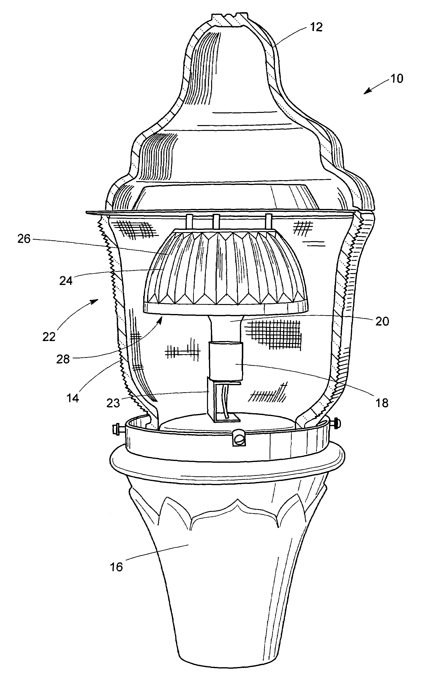
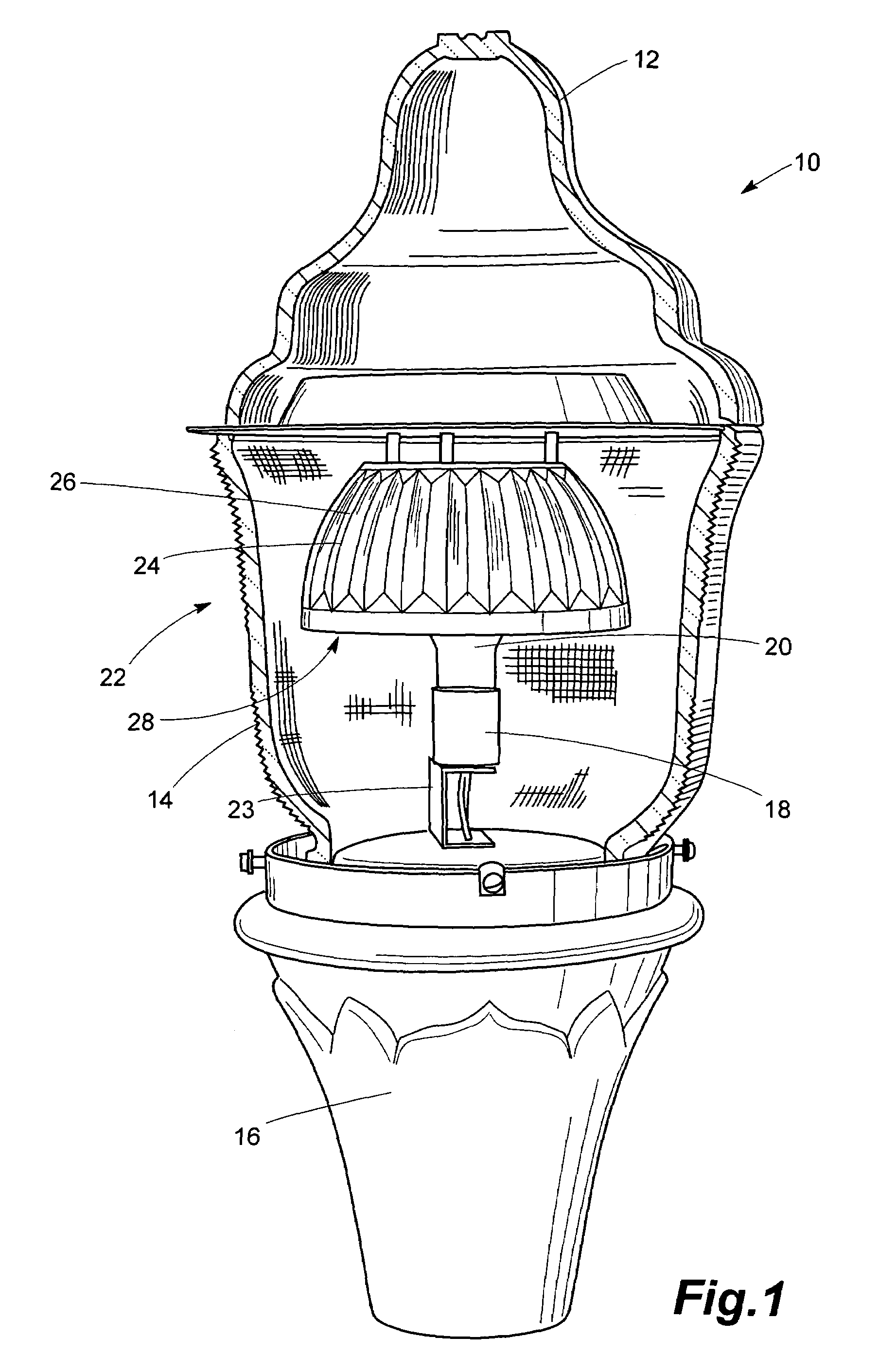
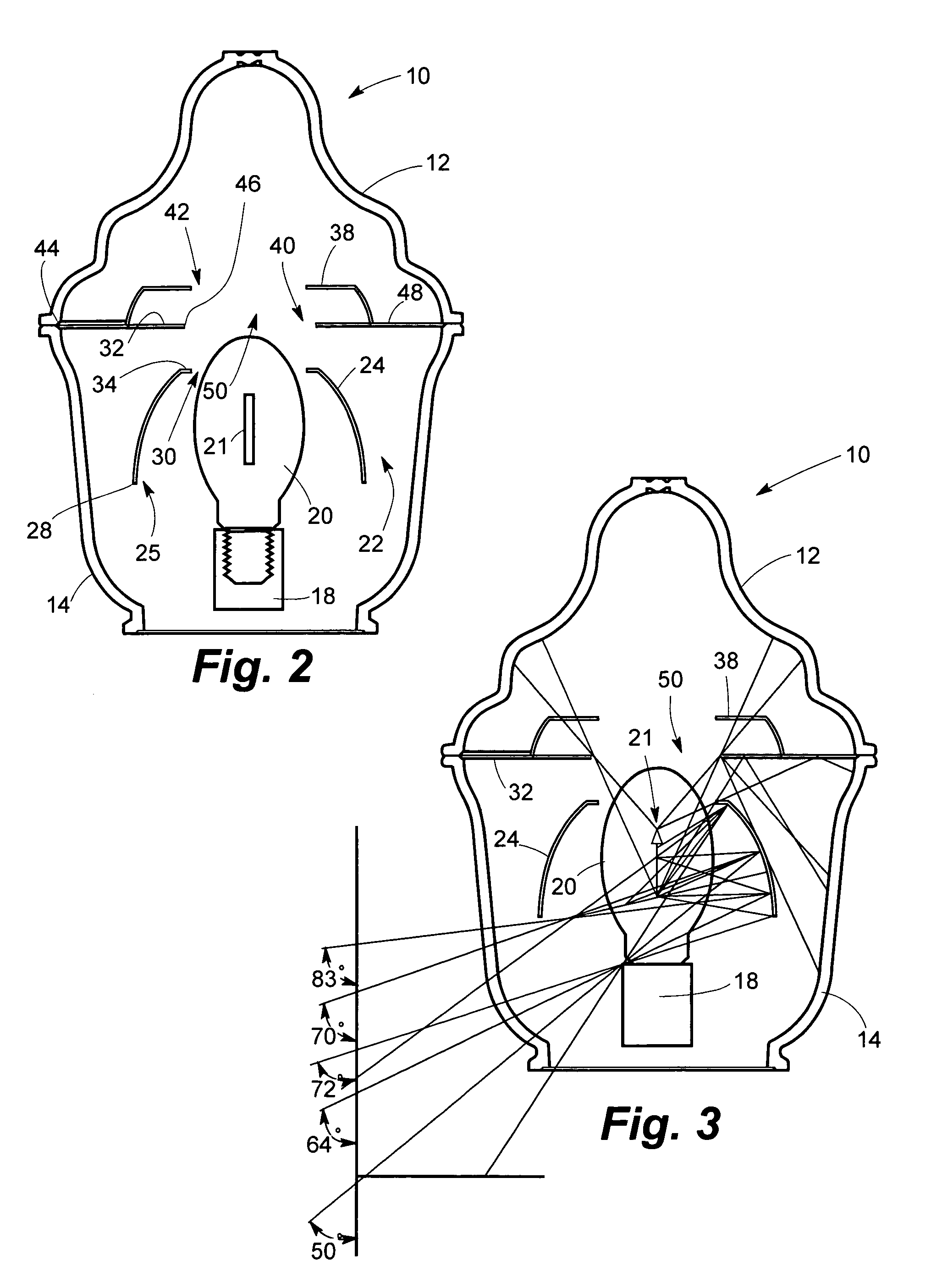
[0036]Preferred embodiments of the invention now shown explicitly in the drawings and described herein usually take the form of luminaire globes such as are mounted to distal ends of poles or such as are suspended in a pendant mounting arrangement such as from an arm extending laterally from a pole or stanchion of known conformation. In the several embodiments of the invention, light distributions conforming to standards promulgated by the Illumination Engineering Society of North America (I.E.S.) are produced, thereby to effectively illuminate an area in the vicinity of those luminaires employing the luminaire globes of the invention while meeting I.E.S. cutoff standards as well as Type II, III and V distributions. The luminaire globes of the invention are further configured to reduce direct uplight while controlling glare and addressing other environmental lighting issues such as urban sky glow and light trespass. In the several embodiments of the invention, classic globe shapes a...


PUM

PropertyMeasurementUnit
anglesaaaaaaaaaa
anglesaaaaaaaaaa
distanceaaaaaaaaaa

Abstract

Luminaire optical assemblies intended for pole-mounted and similar applications and capable of effective I.E.S. cutoff performance while exhibiting desirable light distributions even with vertically oriented lamping, the invention contemplates in primary embodiments light-transmissive reflector/refractor combinations typically formed of glass, acrylics and the like, uplight shielding and reflector assemblies of a variety of configurations being disposed within the reflector/refractor combinations to produce desired cutoff characteristics while preserving daytime appearance during nocturnal operation. In certain embodiments of the invention, uplight is controlled by the several variations of the uplight shielding and reflector assemblies to cause light-transmissive portions of the reflector/refractor combinations to subtly glow and thus produce a desired appearance while also producing cutoff characteristics necessary to reduce urban sky glow and glare. The luminaire optical assemblies further permit achievement of I.E.S. cutoff with vertical tamping while maximizing efficiency.

Description

BACKGROUND OF THE INVENTION[0001]1. Field of the Invention[0002]The invention relates generally to luminaires having reflector / refractor combinations and particularly to such combinations capable of producing desired cutoff characteristics with particular light distributions and either a fully luminous appearance or maintenance of the integrity of the daytime appearance during nocturnal operation.[0003]2. Description of the Prior Art[0004]Outdoor luminaires ordinarily mounted by posts or other stanchions have long been used with ornamental values being attendant to a requirement for a necessary level of illumination of a roadway, street, lane or other outdoor environment. Such post-mounted luminaires are usually each provided with a transparent or translucent globe within which a light source is mounted, the globe having an upper portion usually referred to as a reflector that is ordinarily formed of a light-transmissive material such as glass, acrylic, etc., as is conventional in t...

Claims


Application Information

Patent Timeline
Patent Type & Authority Patents(United States)
IPC IPC(8): F21S8/08F21V3/00F21V3/04F21V7/00F21V7/09F21V7/22F21V13/04
CPCF21S8/081F21V3/04F21V7/0016F21V13/04F21V7/09F21V7/22F21W2131/10F21V7/24F21V7/28
Inventor ABDELSAMED, YASER S.PACKER, MICHAEL
Owner ABL IP HLDG
Why Eureka
Try Eureka