User fee charging system in which traffic is determined through sampling operation
a traffic and user-based technology, applied in the field of user-based fee charging system, can solve the problems of excessive use of communication system resources more than the observed quantity of transfer data, excessive fee is charged to the user, and inability to obtain appropriate account data
- Summary
- Abstract
- Description
- Claims
- Application Information
AI Technical Summary
Problems solved by technology
Method used
Image
Examples
first embodiment
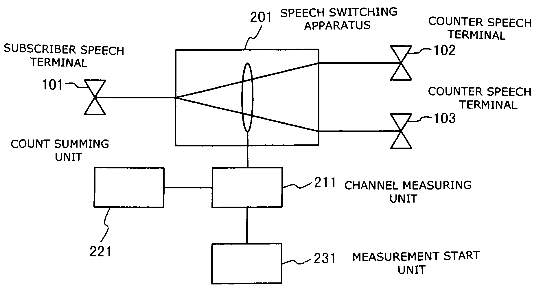
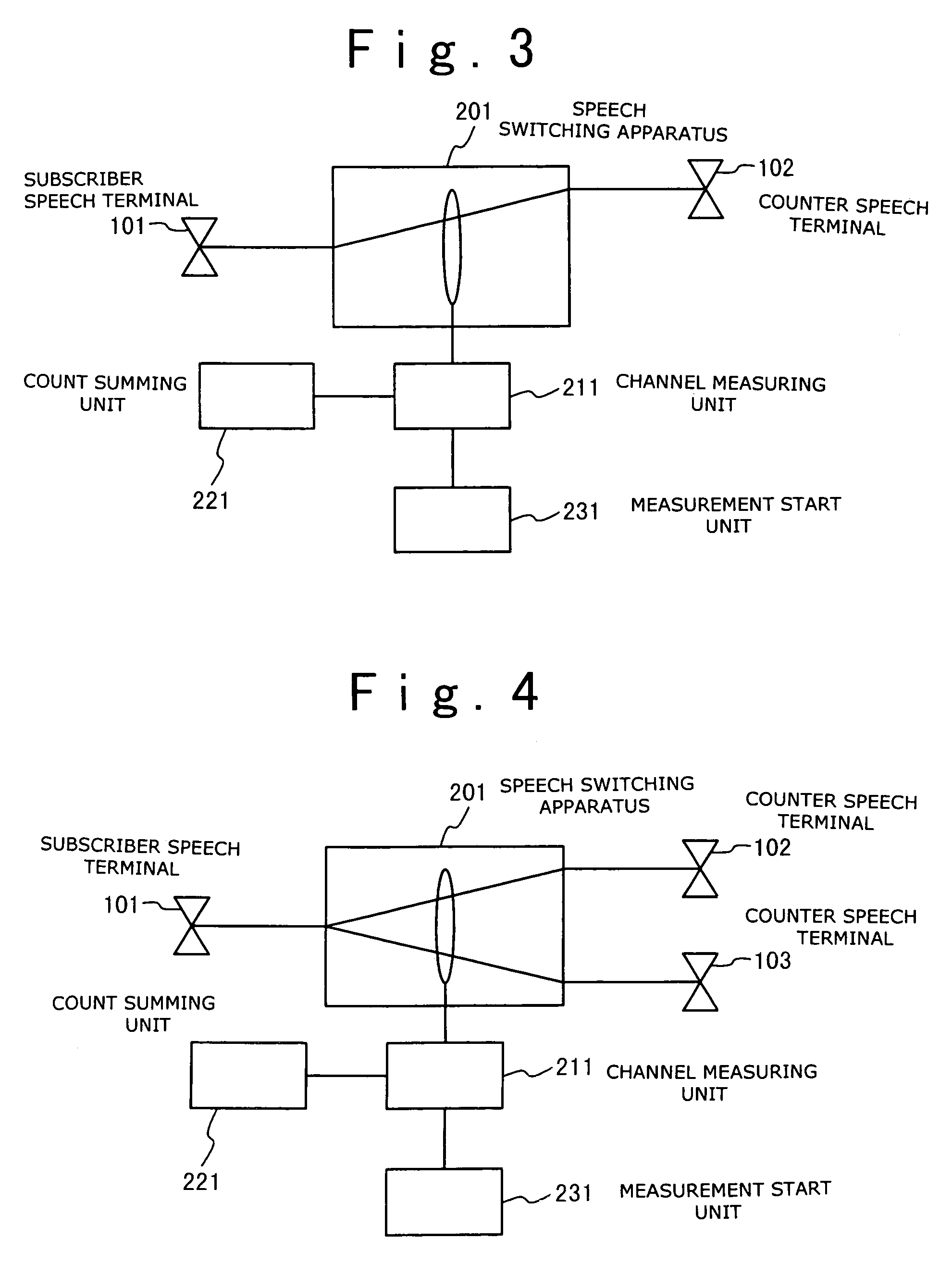
[0043]Next, the communication fee charging system according to a modification of the present invention will be described below with reference to FIG. 4.
[0044]Referring to FIG. 4, the subscriber speech terminal 101 is connected to a plurality of counter speech terminals 102 and 103 in a conference system. The subscriber speech terminal 101 first starts call origination to the counter speech terminal member 102 and then starts call origination to the counter speech subscriber terminal member 103. Thereafter, the subscriber speech terminal 101 ends the communication with the counter speech terminal 102. Thus, the fee charging system measures the account data in the state in which the subscriber speech terminal 101 communicates with the counter speech terminal 103. In this case, the occupied channel measuring unit 211 measures the occupied channel of one when the subscriber terminal 101 communicates with the counter speech terminal 102. The measuring result is periodically outputted to ...
second embodiment
[0048]FIG. 7 is similar to the example shown in FIG. 6 and shows a case where the subscriber data terminal 106 has sessions with counter subscriber data terminals 107 and 108. In this case, like the above example, it is not necessary that the subscriber data terminal 106 continuously carries out data transfer. In the second embodiment, the account data can be collected with no relation to the number of counter data terminals 107 and 108 which have sessions with the subscriber data terminal 106.
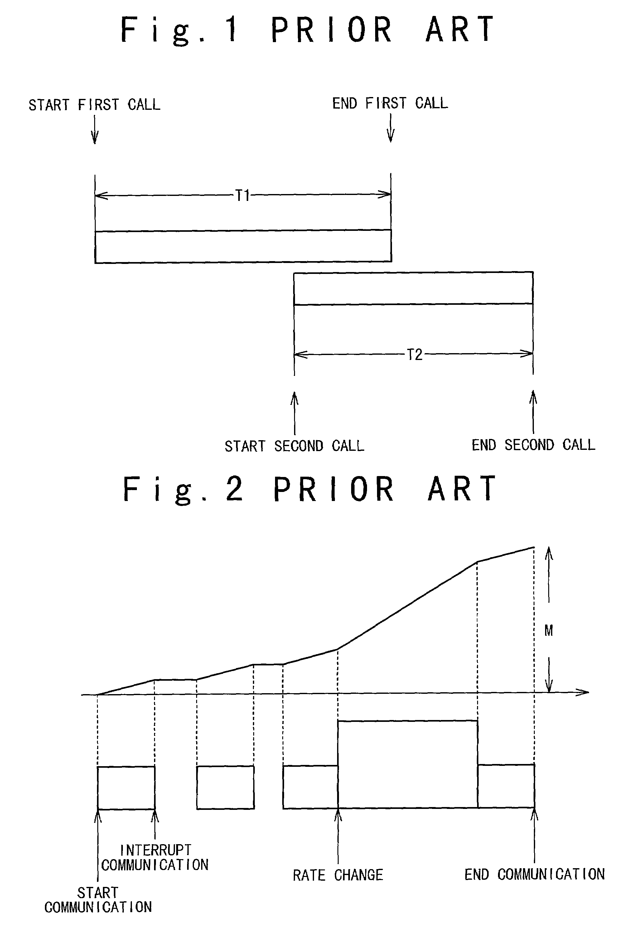
[0049]A specific example of the fee charging system for the packet switching call in the second embodiment will be described with reference FIG. 8. As the feature of the packet switching call, there are rate change and non-transmission interval. The quantity of transfer data of the packet switching call is measured in 13 sampling intervals in FIG. 8.
[0050]As the sampling result, the observation value of “0” is observed as a scan result for no data to be transferred in the first sampling interv...
fourth embodiment
[0058]Next the communication fee charging system according to the present invention will be described. Here, it is possible to change a sampling time interval randomly. For example, it is supposed that a generating apparatus of a packet call has an autonomous clock function and generates packet data periodically. In this case, if the sampling period of the fee charging system is synchronous with the generation period of the packet data by the above-mentioned apparatus, there would be a case that the quantity of transfer data is observed less or more. Therefore, such a case can be prevented in this embodiment.
PUM
 Abstract
Description
Claims
Application Information
 - R&D
- Intellectual Property
- Life Sciences
- Materials
- Tech Scout
- Unparalleled Data Quality
- Higher Quality Content
- 60% Fewer Hallucinations
Browse by: Latest US Patents, China's latest patents, Technical Efficacy Thesaurus, Application Domain, Technology Topic, Popular Technical Reports.
© 2025 PatSnap. All rights reserved.Legal|Privacy policy|Modern Slavery Act Transparency Statement|Sitemap|About US| Contact US: help@patsnap.com


