Dynamic phase aligning interface

a phase alignment and interface technology, applied in the field of communication systems, can solve the problems of large amount of logic required for fifo buffers, and the substantial cost of including the logic required for buffers

Inactive Publication Date: 2005-12-06
INTEL CORP
View PDF4 Cites 22 Cited by
  • Summary
  • Abstract
  • Description
  • Claims
  • Application Information

AI Technical Summary

Problems solved by technology

However, the use of a FIFO buffer generally requires a significant amount of logic.
If the device receiving the data is a high speed device, there are substantial costs involved in including the logic required for the buffer.
A buffer is gene

Method used


Image

  • Dynamic phase aligning interface
  • Dynamic phase aligning interface
  • Dynamic phase aligning interface

Examples


Embodiment Construction

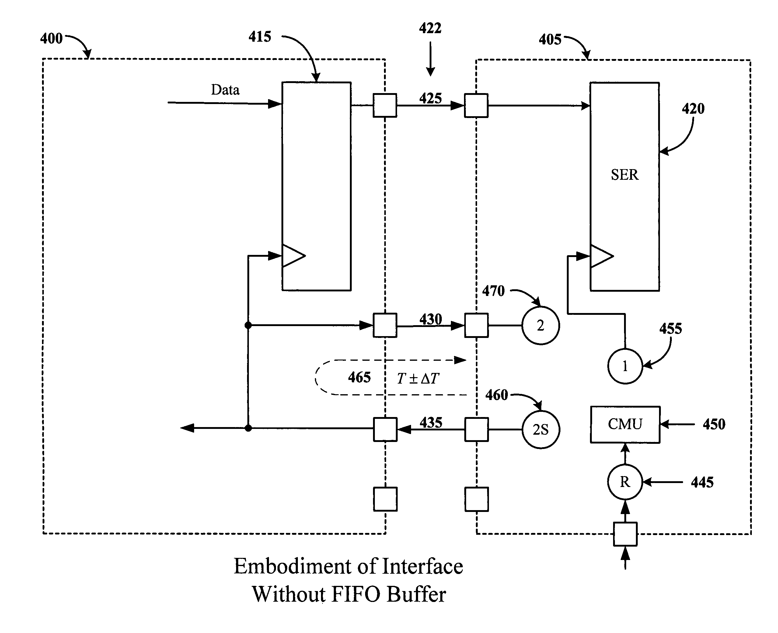
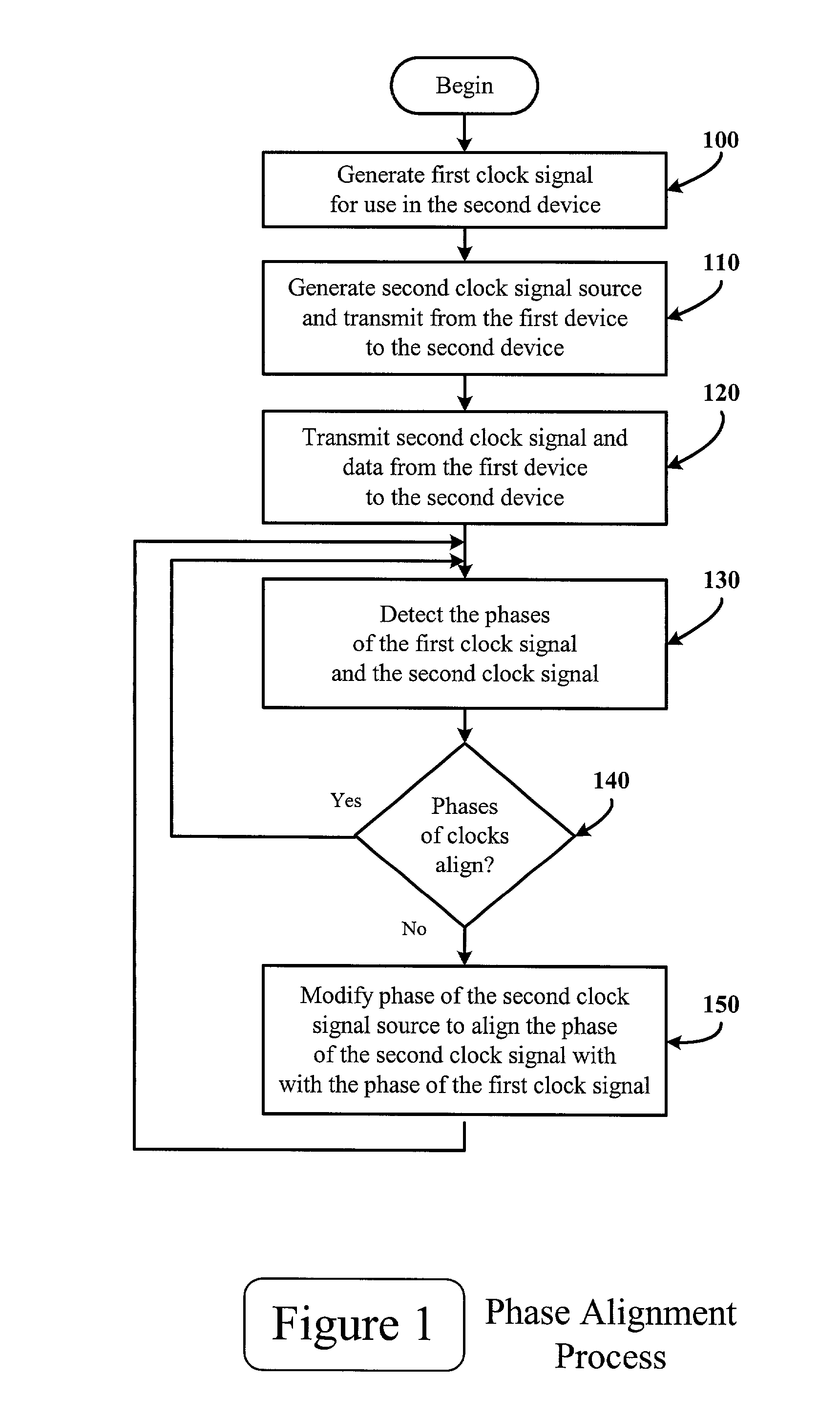
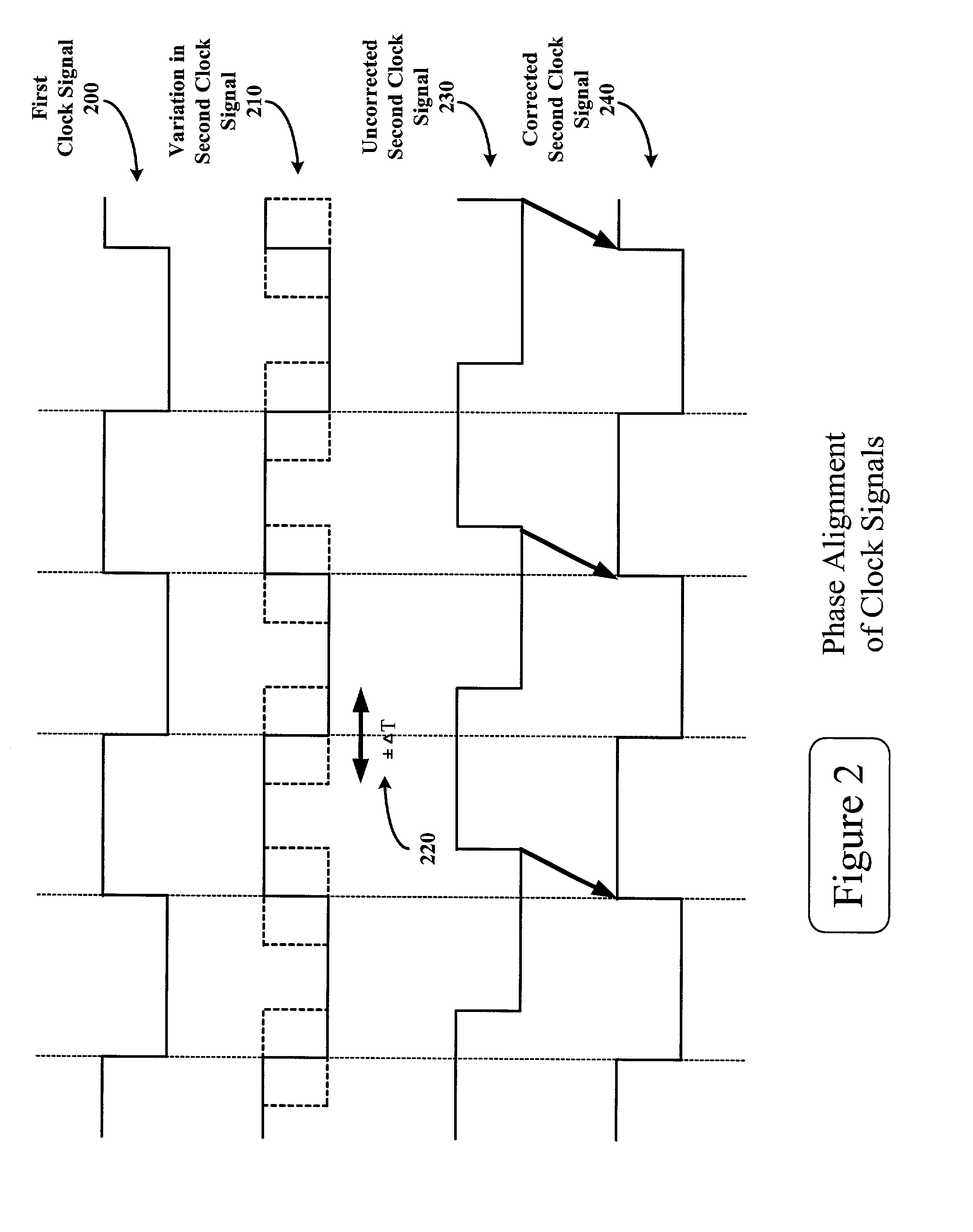
[0011]A method and apparatus are described for a dynamic phase aligning interface.

[0012]In the following description, for the purposes of explanation, numerous specific details are set forth in order to provide a thorough understanding of the present invention. However, it will be apparent to one skilled in the art that the present invention may be practiced without some of these specific details. In other instances, well-known structures and devices are shown in block diagram form.

[0013]The present invention includes various processes, which will be described below. The processes of the present invention may be performed by hardware components or may be embodied in machine-executable instructions, which may be used to cause a general-purpose or special-purpose processor or logic circuits programmed with the instructions to perform the processes. Alternatively, the processes may be performed by a combination of hardware and software.

[0014]This application describes a method and appa...


PUM


Abstract

According one embodiment, an apparatus and method are disclosed for a dynamic phase aligning input interface. In the embodiment, a first device provides data to a second device. According to the embodiment, the interface is counter clocked, the second device being clocked by a first clock signal and providing a second clock signal source to the first device for clocking the data. The first device transmits the second clock signal and the data to the second device, with the second clock signal being delayed by the period of time required for the second clock signal source to propagate through the first device. The second device detects the phase of the first clock signal and the second clock signal and modifies the phase of the second clock signal source to align the phase of the first clock signal and the phase of the second clock signal.

Description

[0001]This application claims priority to U.S. Provisional Application No. 60 / 269,229, filed Feb. 15, 2001, and U.S. Provisional Application No. 60 / 289,555, filed May 8, 2001.FIELD OF THE INVENTION[0002]This invention relates to communication systems in general, and more specifically to a method and apparatus for a dynamic phase aligning interface.BACKGROUND OF THE INVENTION[0003]In a digital interface between two devices, data often is accompanied by a clock signal. In many instances the device that is transmitting the data is also the source of the clock signal. However, in certain instances the receiving device is the source of the clock signal, in which case the interface is said to be counter clocked. A counter clocked interface creates different design considerations than other clock arrangements. The clock signal received by the second device is delayed by the time that it takes for the clock signal source to propagate through the first device. In this case, there is no known...

Claims


Application Information

Patent Timeline
IPC IPC(8): H04J3/06H04L7/00H04L7/02
CPCH04J3/0682H04J3/0685H04L7/0008H04L7/02
Inventor LYSDAL, HENNINGJOHANSEN, EIVIND
Owner INTEL CORP
Why Eureka
Try Eureka