Spray data analysis and characterization system

a data analysis and characterization system technology, applied in the field of aerosol spray characterization, can solve the problems of high cost, high labor intensity, and high labor intensity, and achieve the effect of reducing labor intensity, reducing labor intensity, and reducing labor intensity

Inactive Publication Date: 2005-12-06
PROVERIS SCI CORP
View PDF14 Cites 24 Cited by
  • Summary
  • Abstract
  • Description
  • Claims
  • Application Information

AI Technical Summary

Benefits of technology

[0036]Another embodiment of the invention further includes one or more calibrating components for associating physical coordinates with image coordinates within each of the set of images.
[0037]In another embodiment of the invention, the processor further integrates the set of images so as to exhibit a time-average representation of the images, and measuring one or more parameters of the time average representation.

Problems solved by technology

However, accurate, reliable and easy-to-use protocols and a system for inhaler-based DDD spray characterization do not exist.
One disadvantage to this configuration is that the presence of the TLC plate radically alters the natural fluid dynamics of the spray causing it to switch from a free aerosol jet to an impinging jet.
Another disadvantage to this configuration is that a large of amount of the spray particles bounce off the plate, causing artifacts in the pattern that do not exist in an unconstrained spray.
This is especially problematic for dry powder-based DDDs because the particles don't tend to stick to the TLC plate at all causing artificially low spray pattern densities to be measured and reported.
Yet another disadvantage to this configuration is that the measurements of the spray pattern are very sensitive to the operator's judgement and prone to low reliability.
A further disadvantage to this configuration is that the associated measurement technique is restricted to measurements only of the static aspects of the spray pattern; it cannot be used to investigate any time-evolving or plume geometry properties of the spray.

Method used


Image

  • Spray data analysis and characterization system
  • Spray data analysis and characterization system
  • Spray data analysis and characterization system

Examples


Embodiment Construction

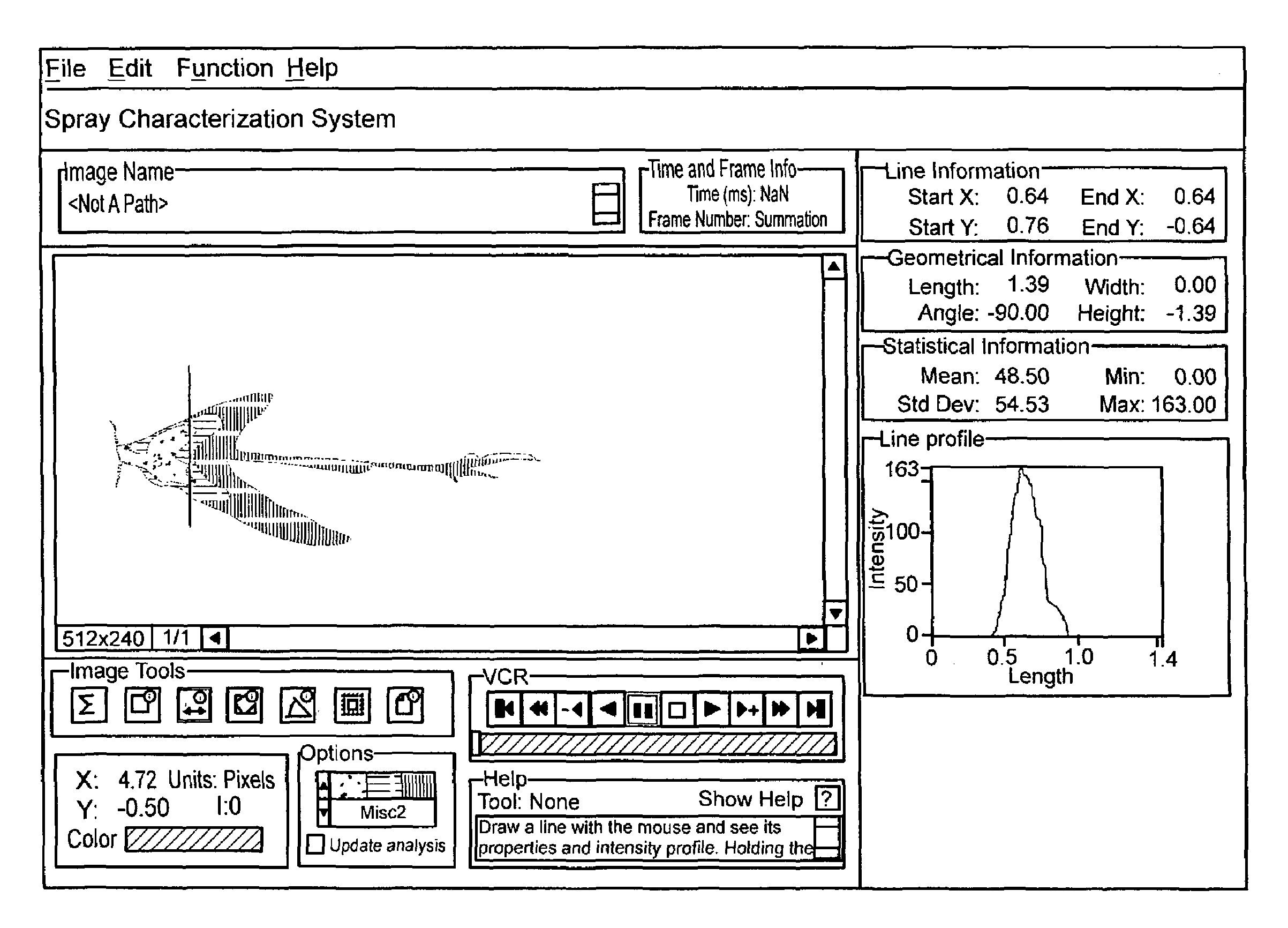
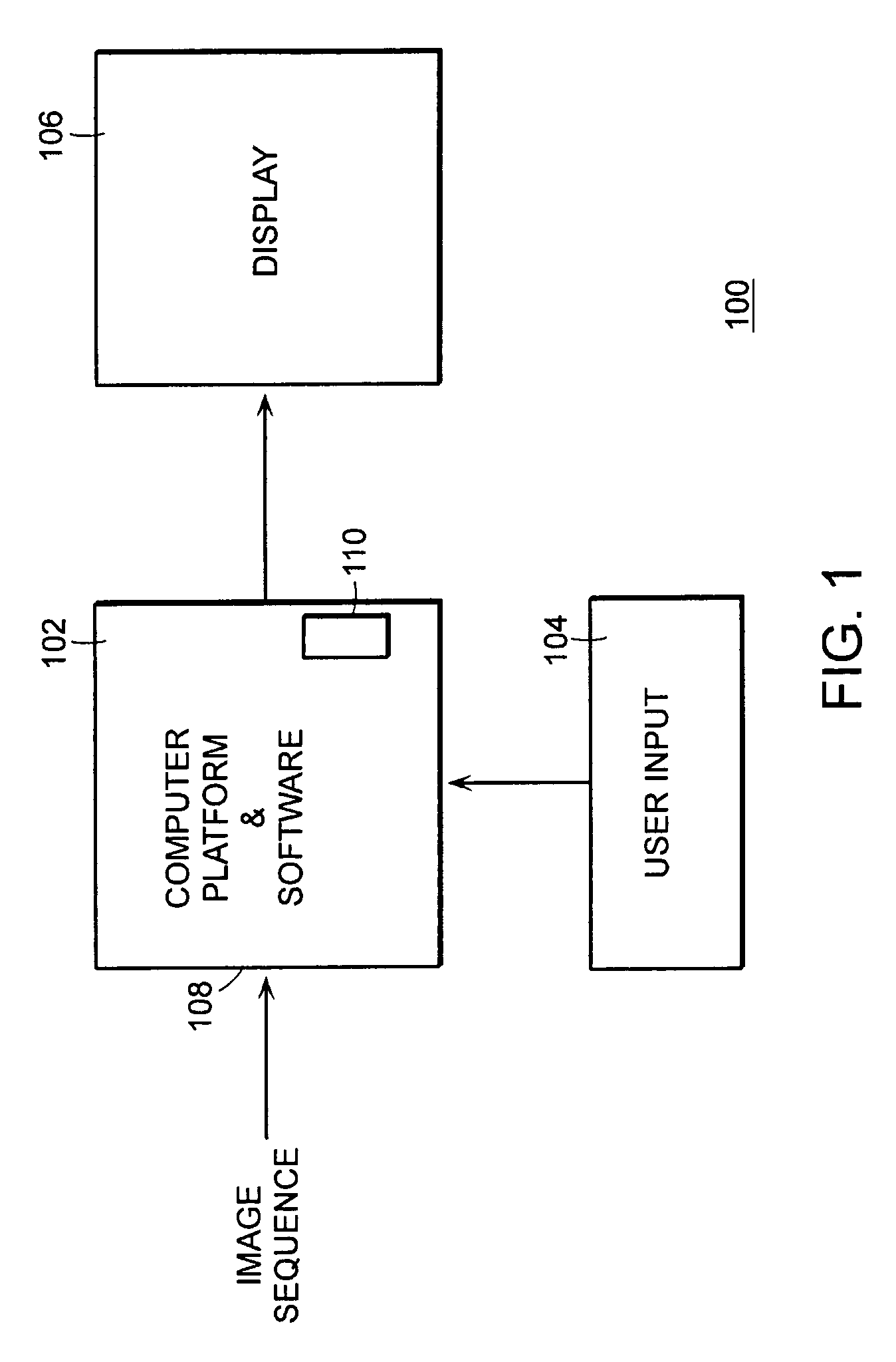
[0049]The spray data analysis and characterization system of the present invention receives data representative of a sequential set of images of a spray plume. Each of the images is preferably representative of a density characteristic of said spray plume (i) along at least one geometric plane that intersects the spray plume, and (ii) at a predetermined instant in time.

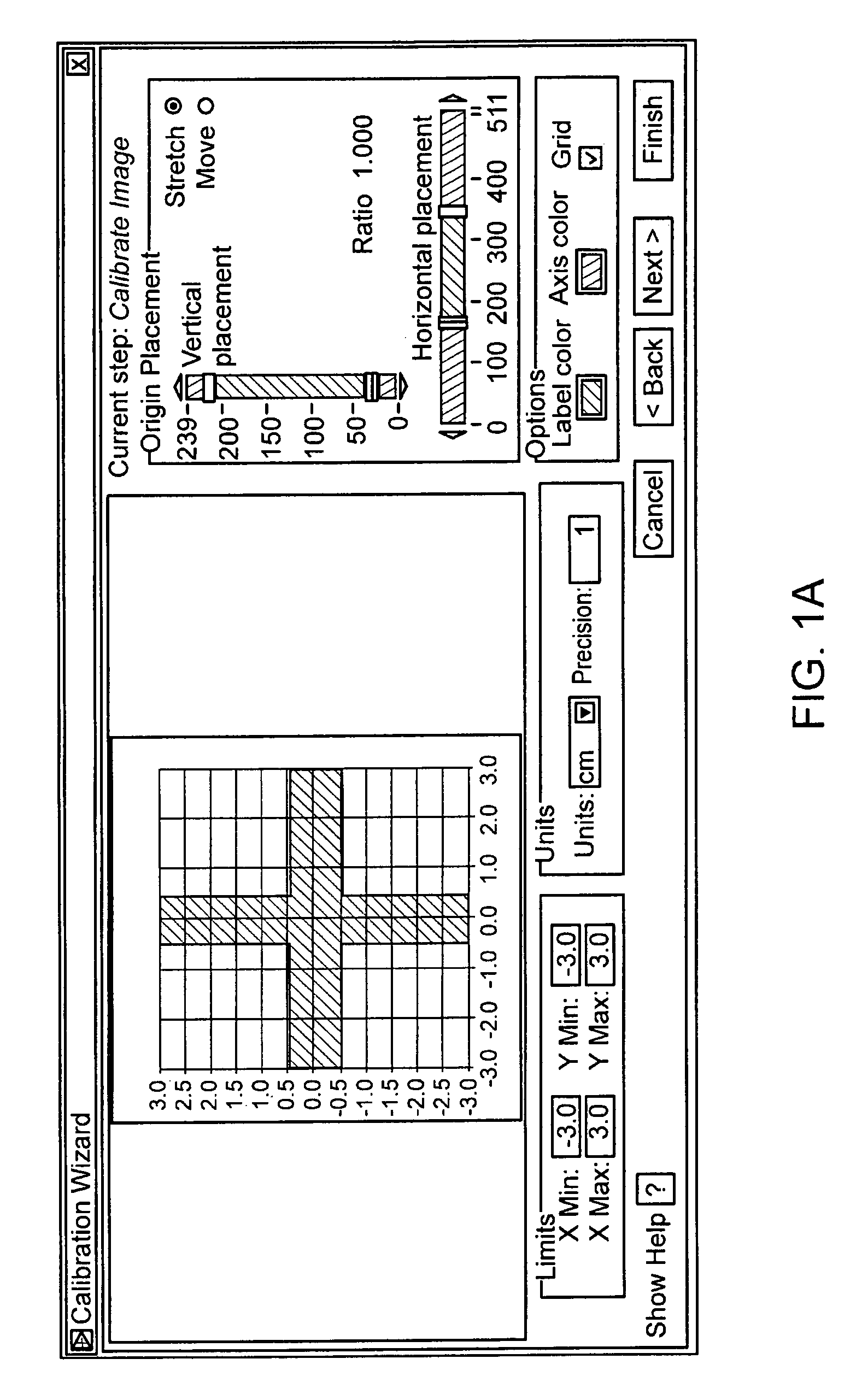
[0050]In one preferred embodiment, one of the geometric planes includes the flow-direction centerline of the spray plume (also referred to herein as the central axis of the spray plume), and one of the geometric planes is perpendicular to the central axis, although the present invention may be used to analyze other planes through the plume. Using the sequential set of images, the system displays a time-evolution of the plume from inception to dissipation, and derives physical parameters of the of the plume, such as particle distribution and divergence angle of spray patterns. In general, the system provides informatio...


PUM


Abstract

A method of and system for analyzing image data representative of a sequential set of images of a spray plume, each of the images being representative of a density characteristic of the spray plume (i) along a geometric plane that intersects the spray plume, and (ii) at a predetermined instant in time, that in one aspect comprises sequentially displaying the set of images so as to exhibit a time evolution of the spray plume along the geometric plane. The invention may further integrate the set of images so as to exhibit a time-average representation of the images. In one embodiment, the invention comprises a general purpose computer executing software that receives and sequentially displays the set of images so as to exhibit a time evolution of the spray plume along the geometric plane, and provides a user interface for measuring one or more spray plume parameters associated with the spray plume within one or more of the images.

Description

RELATED APPLICATIONS[0001]This application is a continuation of U.S. application Ser. No. 09 / 640,346, filed on Aug. 16, 2000, U.S. Pat. No. 6,665,421, which claims the benefit of U.S. Provisional Application No. 60 / 149,171, filed on Aug. 17, 1999. The entire teachings of the above applications are incorporated herein by reference.[0002]This application is related to U.S. application Ser. No. 09 / 640,246 of common assignee, “Spray Data Acquisition System”, inventor Dino J. Farina, filed on Aug. 16, 2000, which claims the benefit of U.S. Provisional Application No. 60 / 149,281, filed on Aug. 17, 1999. The entire teachings of the above applications are incorporated herein by reference.BACKGROUND OF THE INVENTION[0003]The present invention relates to the field of aerosol spray characterization, and more particularly, to computer assisted methods of analyzing and characterizing a set of sequential images corresponding to the progression of an aerosol spray.[0004]The fluid dynamic character...

Claims


Application Information

Patent Timeline
Patent Type & Authority Patents(United States)
IPC IPC(8): G01P5/00A61M15/00G06K9/00G06T7/00G06T7/20G06T7/60
CPCG01P5/001G06T7/20G06T7/60G06T2200/24G06T2207/30108
Inventor FARINA, DINO J.
Owner PROVERIS SCI CORP
Why Eureka
Try Eureka