Wiper blade for motor vehicle windows

a technology for motor vehicles and windows, applied in the direction of vehicle maintenance, vehicle cleaning, domestic applications, etc., can solve the problems of different pressure distribution, unsatisfactory knocking noise, and matching of the stress of the carrying element to the desired pressure distribution, so as to reduce the contact pressure

Inactive Publication Date: 2005-12-13
ROBERT BOSCH CORP
View PDF10 Cites 47 Cited by
  • Summary
  • Abstract
  • Description
  • Claims
  • Application Information

AI Technical Summary

Benefits of technology

[0006]According to the present invention, a wiper blade which can be moved back and forth across the window comprises an elongated wiper strip, and a spring-elastic carrying element wherein a contact force of the wiper strip against the window is greater in its center section then in at least one of two end sections thereof. In the wiper blade according to the present invention, in the vicinity of the reduced contact force, a steeper drag position of the wiper lip is produced in comparison to the region with the greater contact force. This steeper position of the wiper lip encourages its tilting-over

Problems solved by technology

The uniform pressure distribution over the entire wiper blade length desired in both instances, however, causes the wiper lip, which belongs to the wiper blade and does the actual wiping work, to abruptly flip over along its entire length from its one drag position into the other when the wiper blade reverses its working direction.
However,

Method used


Image

  • Wiper blade for motor vehicle windows
  • Wiper blade for motor vehicle windows
  • Wiper blade for motor vehicle windows

Examples


Embodiment Construction

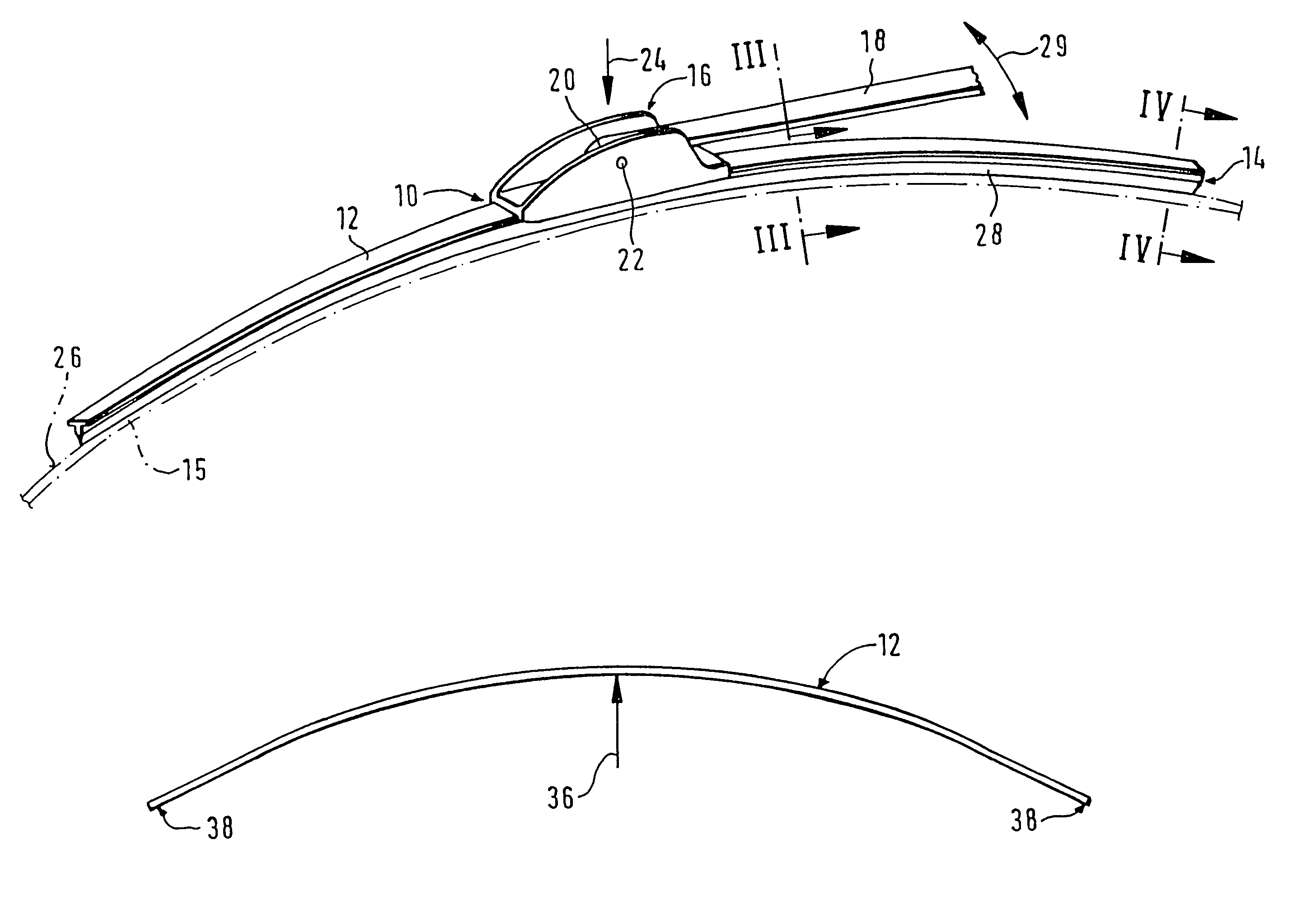
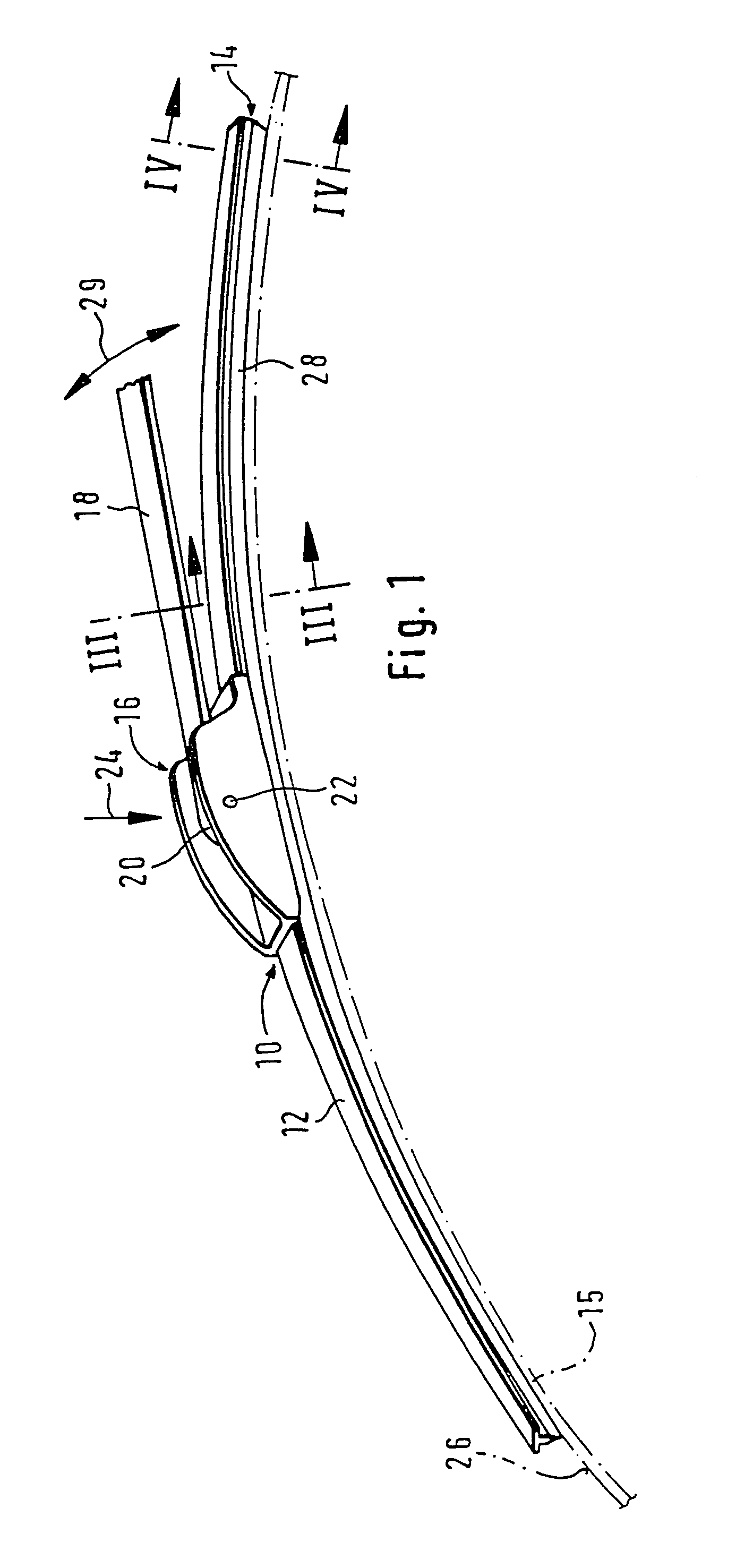
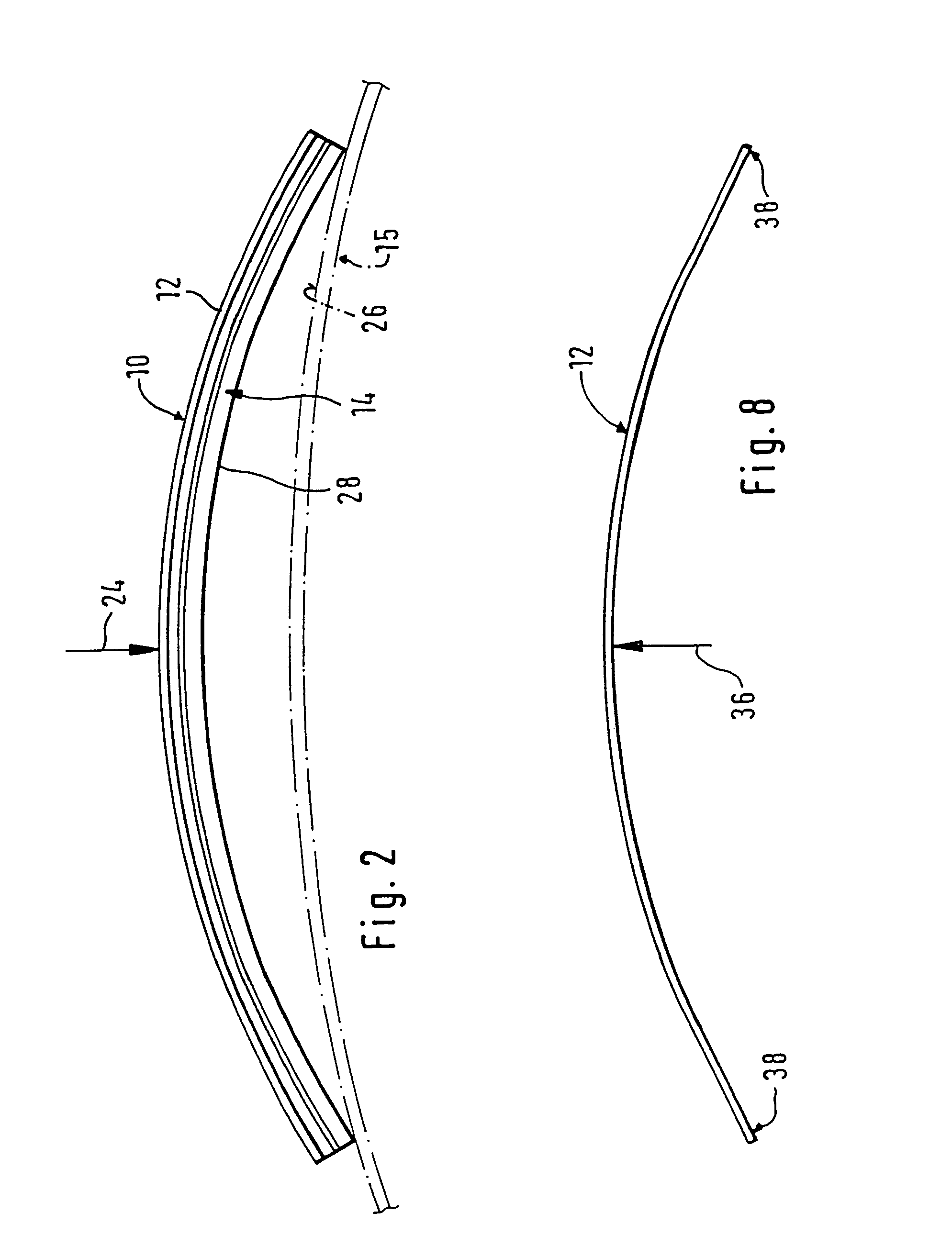
[0019]A wiper blade 10 shown in FIG. 1 has an elongated, spring-elastic carrying element 12 for a wiper strip 14, and this carrying element 12 is shown separately in FIG. 8. As can be seen from FIGS. 1, 3, and 4, the carrying element 12 and the wiper strip 14 are connected to each other so that their longitudinal axes are parallel. A connecting device 16 is disposed on the top side of the carrying element 12 remote from the window 15 to be wiped—indicated with dot-and-dash lines in FIG. 1—and with the aid of this connecting device 16, the wiper blade 10 can be detachably connected to a driven wiper arm 18 that is supported on the body of a motor vehicle. The elongated, rubber-elastic wiper strip 14 is disposed on the underside of the carrying element 12 oriented toward the window 15. A hook, which is used as a reciprocal connecting means, is formed onto the free end 20 of the wiper arm 18 and encompasses a pivot bolt 22 belonging to the connecting device 16 of the wiper blade 10. Th...


PUM


Abstract

A wiper device with a wiper blade for cleaning windows of motor vehicles, in which the wiper blade can be moved back and forth laterally to its longitudinal span by a driven wipe arm which can be connected to the wiper blade and loads the same against the window. The wiper blade has an elongated wiper strip that can be placed against the window and an elongated spring-elastic carrying element, which has a connecting unit for the wiper arm and is disposed parallel to the longitudinal axis of the wiper strip to distribute a contact force over the entire wiper strip length. A particularly effective and low-noise operation of the wiper system is achieved because the contact force of the wiper strip against the window is greater in its center section than in at least one of two end sections of the wiper strip.

Description

[0001]This application is a 371 of PCT / DE98 / 03721 filed Dec. 18, 1998.PRIOR ART[0002]In wiper blades of the type under consideration, the carrying element is intended to assure a predetermined distribution of the wiper arm-induced wiper blade pressing force—often also called pressure—against the window over the entire wiping field swept across by the wiper blade. Through a corresponding curvature of the unstressed carrying element—i.e. when the wiper blade is not resting against the window—the ends of the wiper strip, which is placed completely against the window during the operation of the wiper blade, are loaded toward the window by the carrying element which is then stressed, even when the curvature radii of spherically curved vehicle windows change with each wiper blade position. The curvature of the wiper blade must therefore be slightly sharper than the sharpest curvature measured in the wiping field on the window to be wiped. The carrying element consequently replaces the exp...

Claims


Application Information

Patent Timeline
IPC IPC(8): B60S1/38
CPCB60S1/38B60S1/3875B60S2001/3818
Inventor KOTLARSKI, THOMAS
Owner ROBERT BOSCH CORP
Why Eureka
Try Eureka