Fuel cell system
a fuel cell and system technology, applied in the direction of fuel cell control, electrochemical generators, chemistry apparatus and processes, etc., can solve the problems of wasting generated power, corresponding worsening fuel economy, etc., and achieve the effect of not consuming excessive energy
- Summary
- Abstract
- Description
- Claims
- Application Information
AI Technical Summary
Benefits of technology
Problems solved by technology
Method used
Image
Examples
first embodiment
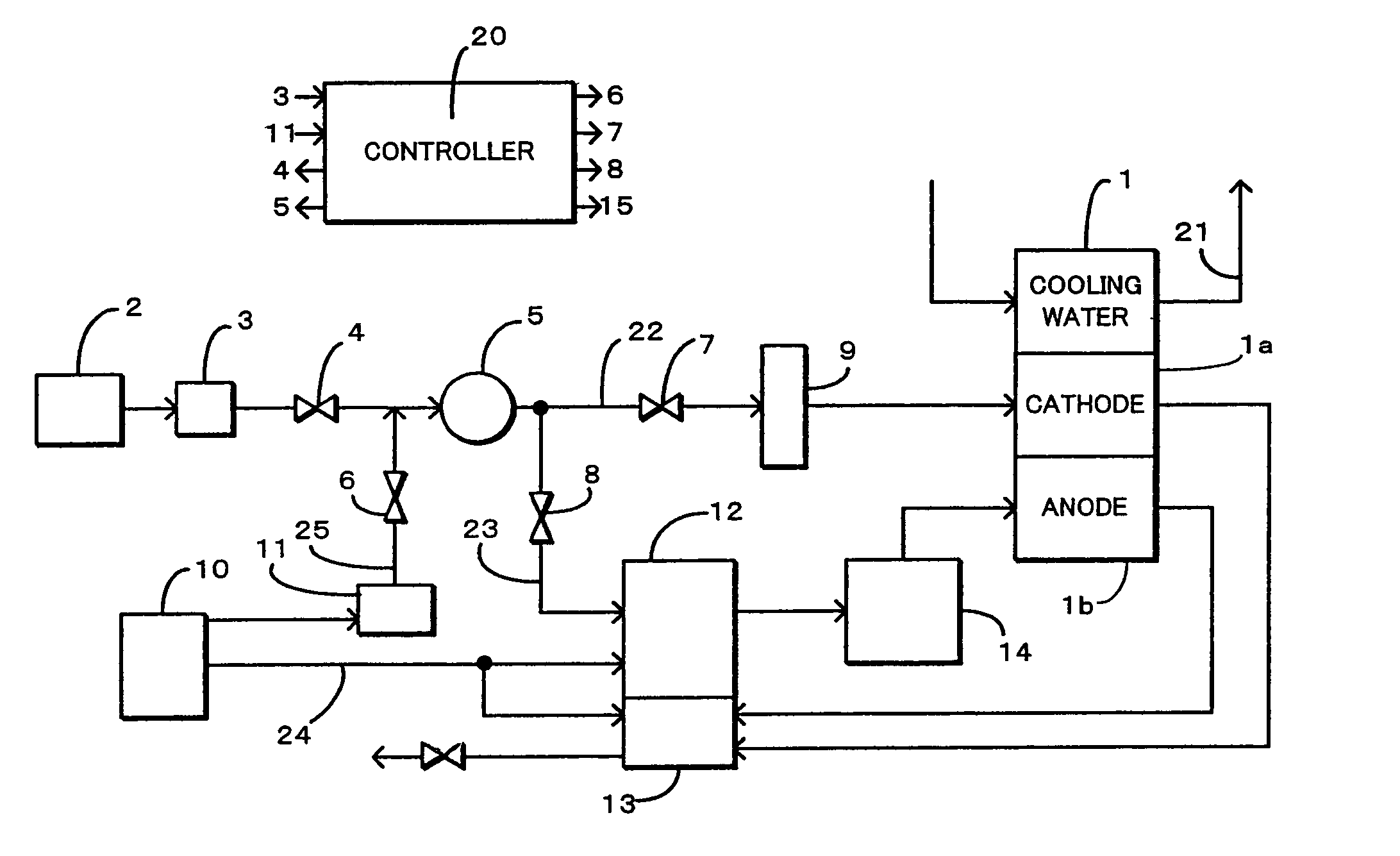
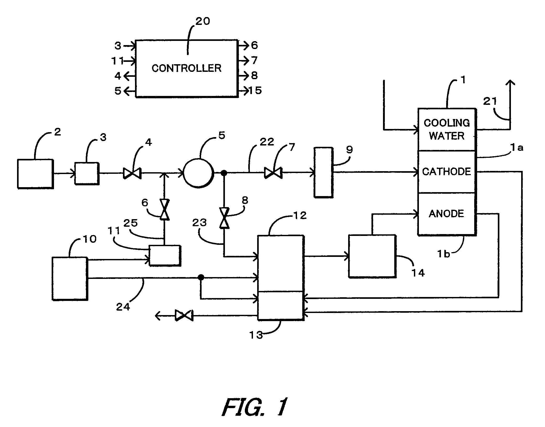
[0023]Referring to FIG. 1 of the drawings, FIG. 1 shows a fuel cell system in a Air containing oxygen is supplied to a cathode 1a of a fuel cell 1 from an air supply system 22, and hydrogen-rich fuel gas is supplied to an anode 1b of the fuel cell 1 from a fuel supply system 24. The fuel cell 1 generates electrical energy and water by transporting hydrogen ions between the electrodes. At this time, heat energy is also produced, and the fuel cell 1 is maintained at a suitable temperature by cooling water which flows through a cooling system 21 so that power is efficiently generated.
[0024]A filter 2 for removing dust from the air, a flowmeter 3 which measures the supplied air amount, a throttle valve 4 which adjusts the supplied air volume, a compressor 5 which delivers pressurized air with an adjusted flowrate, a shutoff valve 7 which controls the supply of air to the fuel cell 1, and a cooler 9 for adjusting the air temperature which has risen in the compressor 5, to a suitable tem...
fourth embodiment
[0070]FIG. 13 shows the construction of a cell system according to a
[0071]In this embodiment, the flowpath which branches off downstream of the compressor 5 is divided into a branch passage 23 which branches off to the reformer 12 via the shutoff valve 8, and a flowpath 26 which branches off to the burner 13 via the shutoff valve 16. Herein, the branch-off point of the branch passage 26 from the air supply passage 22 is arranged on the side of the compressor 5, and the branch-off point of the branch passage 23 from the air supply passage 22 is arranged on the side of the shutoff valve 7 which is downstream therefrom. Due to this construction, fuel vapor can be supplied to one of the reformer 12 and burner 13 according to the state of the system.
second embodiment
[0072]Also, the reformer temperature sensor 30, burner temperature sensor 31, CO oxidizer temperature sensor 32 and fuel cell temperature sensor 33 are installed identically to the
[0073]The controller 20 performs the purge treatment shown in FIG. 14.
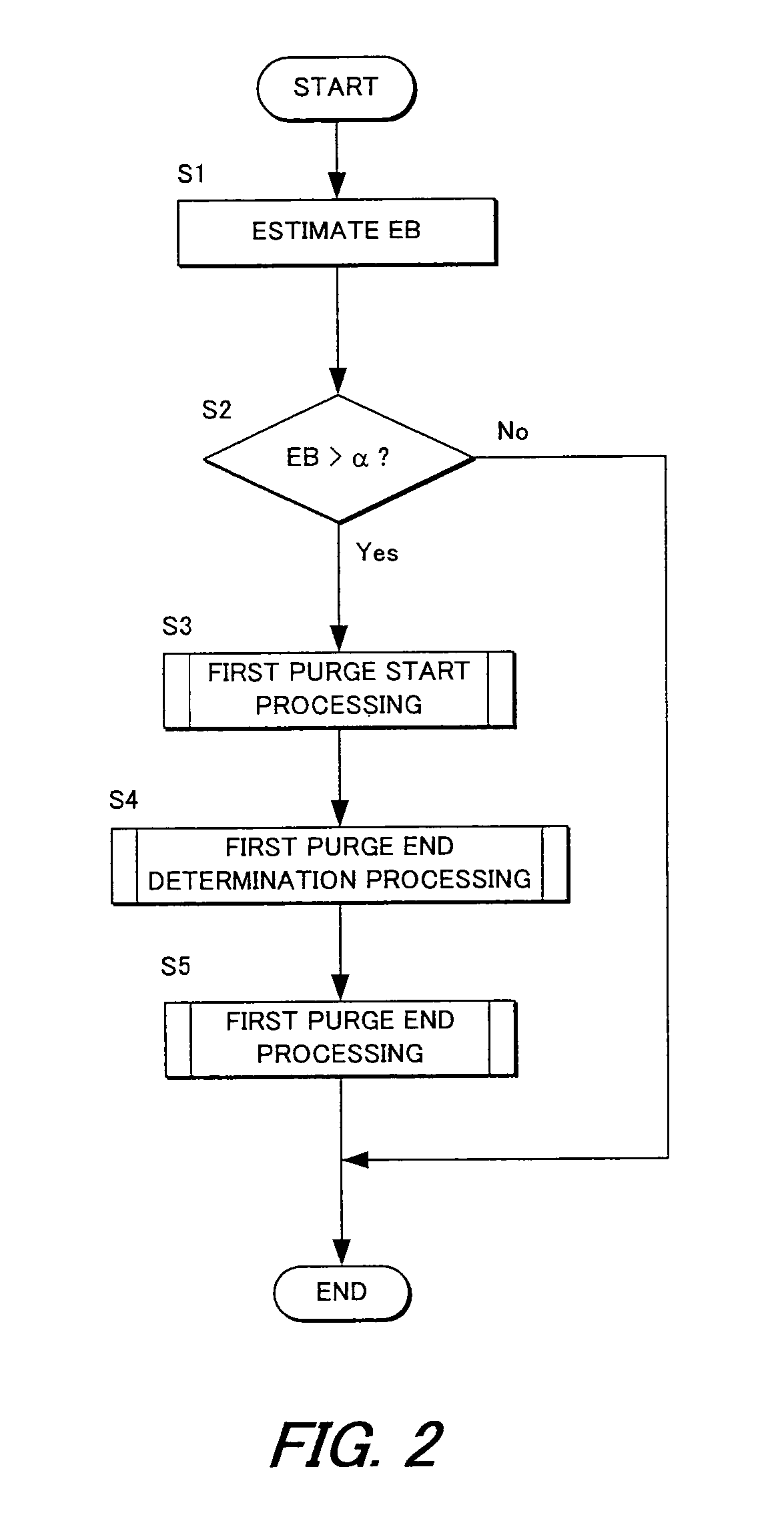
[0074]In steps S31, S32, it is determined whether or not fuel vapor should be purged from the fuel vapor absorption amount EB absorbed by the canister 11. If this is not necessary, the routine is terminated, and if it is necessary, the routine proceeds to a step S33 where it is determined whether or not the system is cold (prior to warmup). If it is determined that the system is cold, a second purge start processing (step S42) which uses fuel vapor in the burner 13, first purge end processing (step S43) and second purge end processing (step S44) are performed, and the vehicle returns to ordinary running.
[0075]On the other hand, if it is determined in the step S33 that the system has warmed up, it is determined in steps S37, S38 whether o...
PUM
| Property | Measurement | Unit |
|---|---|---|
| pressure | aaaaa | aaaaa |
| temperature | aaaaa | aaaaa |
| energy | aaaaa | aaaaa |
Abstract
Description
Claims
Application Information
 - R&D
- Intellectual Property
- Life Sciences
- Materials
- Tech Scout
- Unparalleled Data Quality
- Higher Quality Content
- 60% Fewer Hallucinations
Browse by: Latest US Patents, China's latest patents, Technical Efficacy Thesaurus, Application Domain, Technology Topic, Popular Technical Reports.
© 2025 PatSnap. All rights reserved.Legal|Privacy policy|Modern Slavery Act Transparency Statement|Sitemap|About US| Contact US: help@patsnap.com


