System and method for facilitating fluid three-dimensional movement of an object via directional force

a three-dimensional movement and directional force technology, applied in the field of aerial cable rail systems, can solve the problems of inability to achieve the full spectrum of platform stability, and inability to allow for simple control of the cables in the system

Inactive Publication Date: 2005-12-13
FORTRESS CREDIT CORP AS AGENT
View PDF42 Cites 29 Cited by
  • Summary
  • Abstract
  • Description
  • Claims
  • Application Information

AI Technical Summary

Benefits of technology

[0018]In an embodiment of the invention configured for example in a rectangular configuration with four regions having any appropriate number of line support elements, the supported object is moved along the X-axis independently of movement along the Y-axis and therefore requires no complex control system. In this example, the Z-axis movement follows an ellipsoidal path (four foci ellipsoidal where the foci are the supports) that can be as flat or circular as desired depending on the shape of the area of coverage desired. In the case of an area of coverage over a physical potential well, for example a stadium or open pit mine that is deeper in the middle than on the sides, the X-axis and Y-axis motion can be configured with more or less line in the system to create a flatter or rounder elliptical shape in order to avoid the surface below since the Z-axis automatically traverses vertically when the object moves towards the sides of the area of coverage of the invention. The ellipsoidal path can be as flat or circular as desired depending upon the amount of line deployed in the system and the relative height of the supports. Displacing equal lengths of line into a plurality of sides of the supported object allows the Z-axis of the platform to be traversed which results in trivial control of the object. This technique of relocating line without the need for a control system in order to move an object in three dimensions provides many advantages over the prior art that requires complex control software and active stabilization.
[0019]Embodiments of the invention can also use a three support triangular configuration where no two sides are required to be the same length. For any topology that embodiments of the invention are configured, there is no ratcheting movement at the object since the same line supports an object on a plurality of sides with the object freely moving to the point of minimal potential energy based on the amount of line transferred from one side to another side of the supported object. In addition, the lengths of the line do not require adjustment in way that requires complex calculations and computer control since the junctions effecting movement of each axis are independently operated.

Problems solved by technology

Many of these systems are impractical or difficult to use in that such systems typically fail to satisfactorily achieve the full spectrum of platform stability, ease of control, a compact footprint, ease of transport, speed, load bearing, extensibility, maintainability and platform stability.
The '444 and '664 patents minimize the amount of cable in the system but do not allow for simple control of the cables in the system since the speeds and lengths of each cable must change non-uniformly depending upon the path of motion of the supported object.
During the 1920's work was begun on stabilizing cameras carried in vehicles since the movement of the vehicles was limiting the quality of the photographs obtained.
Furthermore, the invention does not provide simple X, Y and Z independence for control purposes and it appears that complex sensing devices must be deployed in order to keep the cables tensioned properly.
The payload is limited and the support structure is small scale.
Also, the invention would not appear to allow the Z-axis to vary beneath the cube, and the size of the cube support structure to service a large volume of space would be extremely expensive to build on the scale required.
Again, complex control is required to keep the tension in all of the ropes at the correct level during movement of the supported equipment.
Mounting heavy motors high in the rigging presents a major safety issue given that suspension lines can break.
The size of the motors limits the payload that can be carried, and further limits the speed at which the payload can be carried.

Method used


Image

  • System and method for facilitating fluid three-dimensional movement of an object via directional force
  • System and method for facilitating fluid three-dimensional movement of an object via directional force
  • System and method for facilitating fluid three-dimensional movement of an object via directional force

Examples


Embodiment Construction

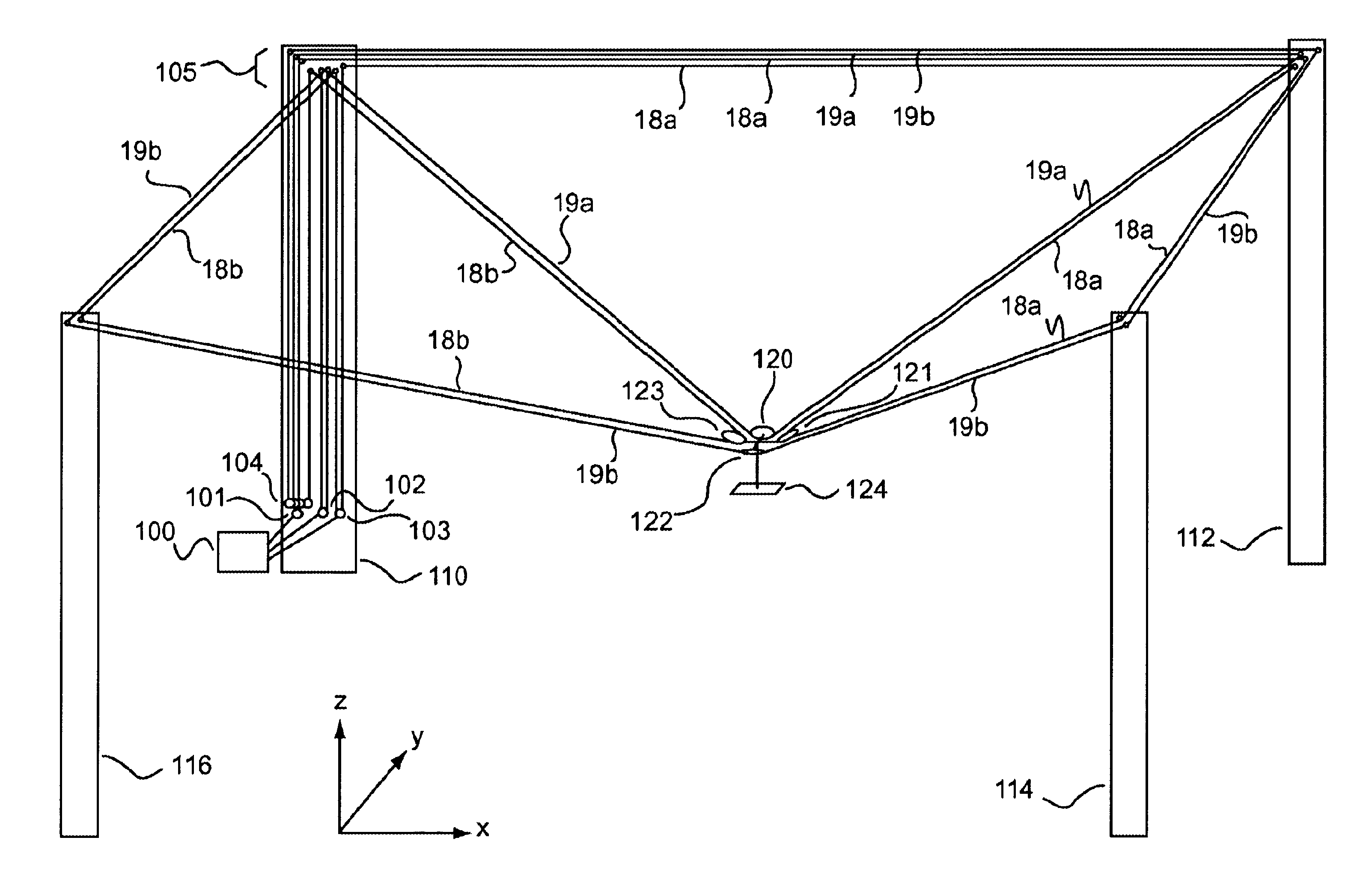
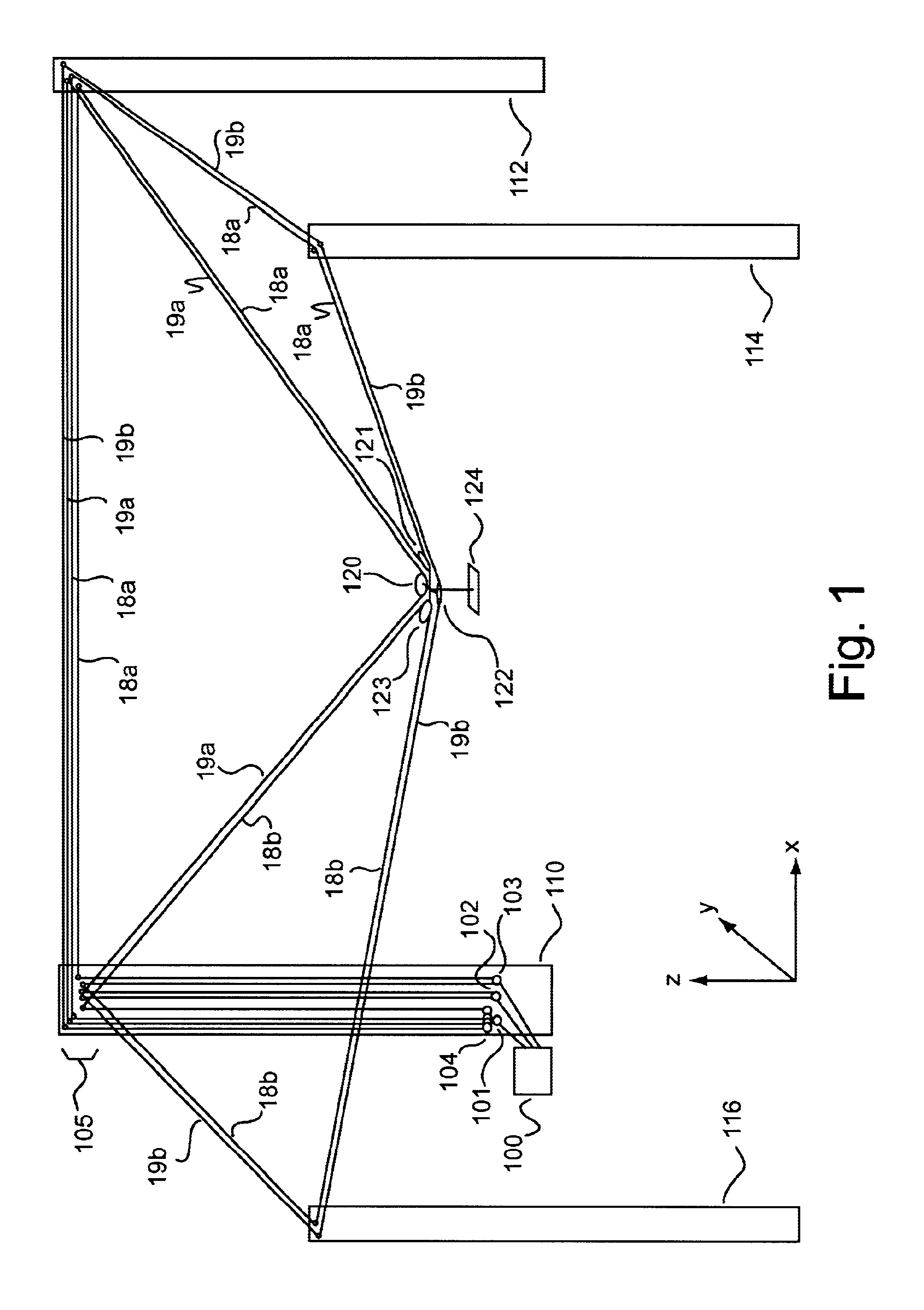
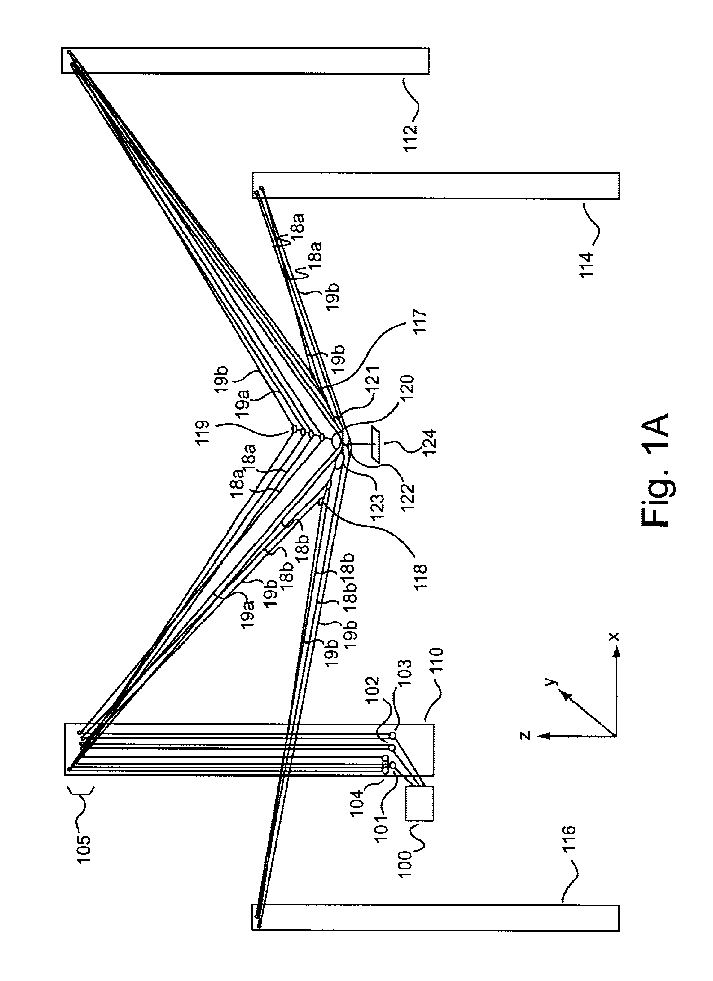
[0075]Embodiments of the invention are ideally suited for moving objects through three-dimensional space using one to more lines. Various embodiments of the invention are capable of positioning an object such as a human, animal, mining implement, logging implement, manufactured object or any other useful object. Embodiments of the invention may, for example, be used in filming movies, sporting events, or any other activity that benefits from fluid movement of a camera or other object to any position within a defined volume of space.

[0076]In the following description, numerous specific details are set forth to provide a more thorough description of embodiments of the invention. It will be apparent, however, to one skilled in the art, that the invention may be practiced without these specific details. In other instances, well known features have not been described in detail so as not to obscure the invention. However, in each instance the claims and the full scope of any equivalents a...


PUM


Abstract

Embodiments of the invention are ideally suited for use filming movies, sporting events, or any other activity that requires fluid movement of a camera or other object to any position within a defined volume of space. To accomplish such positioning embodiments of the invention are configured to move an object throughout three-dimensional space by relocating one or more lines that are feed through a plurality of opposing sides of the object. These line(s) (e.g., a cable, rope, string, cord, wire, or any other flexible connective element) which support the object from above or below the object within a volume of space are arranged in way that allows the object to be rapidly moved to and from any location within the defined volume of space. For instance, the system may be arranged to perform dimensional movement using one line configured as an endless loop, one line configured as a half loop, two lines configured as endless loops or two lines configured as half loops. Other embodiments which split the two lines at the X and Y junctions may yield three and four rope embodiments which are in keeping with the spirit of the invention.

Description

BACKGROUND OF INVENTION[0001]This application is a continuation in part of U.S. patent application Ser. No. 10 / 604,525, filed on Jul. 28, 2003 entitled “System and Method for Moving Objects within Three-Dimensional Space”, now U.S. Pat. No. 6,809,495, which is hereby incorporated herein by reference. This application is a continuation in part of U.S. patent application Ser. No. 10 / 708,158, filed on Feb. 12, 2004 entitled “Cabling System and Method for Facilitating Fluid Three-Dimensional Movement of a Suspended Camera” which is hereby incorporated herein by reference.FIELD OF THE INVENTION[0002]Embodiments of the invention described herein pertain to the field of aerial cable rail systems. More particularly, these embodiments enable the movement of objects within three-dimensional space.DESCRIPTION OF THE RELATED ART[0003]An aerial cable rail system is a system based on an elevated cable or rope, along which objects are transported.[0004]Existing cable rail systems rely on large fix...

Claims


Application Information

Patent Timeline
Patent Type & Authority Patents(United States)
IPC IPC(8): B64C17/06B66C13/08B66C21/00G06TG06T13/00
CPCB66C13/08B66C21/00F16M11/42B25J9/0078F16M11/043F16M11/12F16M11/18F16M11/425
Inventor RODNUNSKY, JIMMACDONALD, S. ALEXANDER
Owner FORTRESS CREDIT CORP AS AGENT
Why Eureka
Try Eureka