Method and apparatus for path planning, selection, and visualization

a robotic and path technology, applied in the field of robotics, can solve the problems of difficult assignment of new movements, difficult to quickly discern the orientation of the robot at any particular location along the travel path, and impose a number of limitations, so as to simplify the process of navigating the device through space, respond faster, and facilitate teleoperation.

Inactive Publication Date: 2010-09-23
SANDBERG ROY
View PDF0 Cites 206 Cited by
  • Summary
  • Abstract
  • Description
  • Claims
  • Application Information

AI Technical Summary

Benefits of technology

[0008]In one embodiment of the invention, a path spline visually represents the current trajectory of the robot through a three dimensional space such as a room. By altering a graphical representation of the trajectory—the path spline—an operator can visualize the path the robot will take, and is freed from real-time control of the robot. Control of the robot is accomplished by periodically updating the path spline such that the newly updated spline represents the new desired path for the robot. This method does not require computationally expensive algorithms to recognize objects in the visual space, and the motion-path of the robot can be updated while the robot is still moving, resulting in a time-efficient movement scheme that does not suffer from the time lag effects or real-time interaction of traditional joystick-based control.
[0009]In another embodiment of the invention, a sensor located on the robot senses the presence of boundaries (obstacles) in the current environment, and generates a path that circumnavigates the boundaries, while still maintaining motion in the general direction selected by the operator. The mathematical form of the path that circumnavigates the boundaries may be a spline. This frees the operator from planning out complex move sequences while still allowing the operator to visualize and correct for improper automated path generation. Furthermore any operator error resulting from selecting a path that nearly intersects or intersects an obstruction is gracefully corrected.
[0010]In another embodiment of the invention, the visual representation of the robot's environment is modified to represent its location at the time the visual representation is displayed for a remote user, based on an analysis of the robots present speed and direction and an estimate of the time-of-flight for information over the telecommunications data link being used. This modification of the visual representation may consist of digitally zooming in by an amount equal to the calculated future forward motion of the robot, and digitally panning left, right, up, or down based on the calculated future forward angular velocity of the robot. In addition, objects moving in the robots field of view, may also be placed in their calculated future position using feature detection techniques known in the art of computer vision. This allows the operator to plan new move sequences on-the-fly based on a simulation of the current conditions the robot is encountering. Therefore the operator can respond more quickly and can move the device at a higher velocity, resulting in more efficient tele-operation.
[0011]In another embodiment of the invention, the device corrects for errors in its movement path due to wheel slip by comparing its actual position with the position predicted by wheel position sensors. The invention allows an operator to pan and tilt the device's camera while this error correction is occurring without impacting the accuracy of the movement path correction.
[0012]In another embodiment of the invention, the device automatically displays suggested paths to the user when likely paths are detected, simplifying the process of navigating the device through a space. The suggested paths are displayed as splines or other lines superimposed on the image of the space through which the device is moving.

Problems solved by technology

However, unique problems arise when, instead of an autonomous robot, a human is controlling a remote controlled surrogate presence (henceforth referred to as a Mobile Video Teleconferencing Device, or “MVTD”).
This imposes a number of limitations.
On the fly assignment of new movements is difficult.
Also, the orientation of the robot at any particular location along its travel path can not be readily discerned by the user.

Method used


Image

  • Method and apparatus for path planning, selection, and visualization
  • Method and apparatus for path planning, selection, and visualization
  • Method and apparatus for path planning, selection, and visualization

Examples


Embodiment Construction

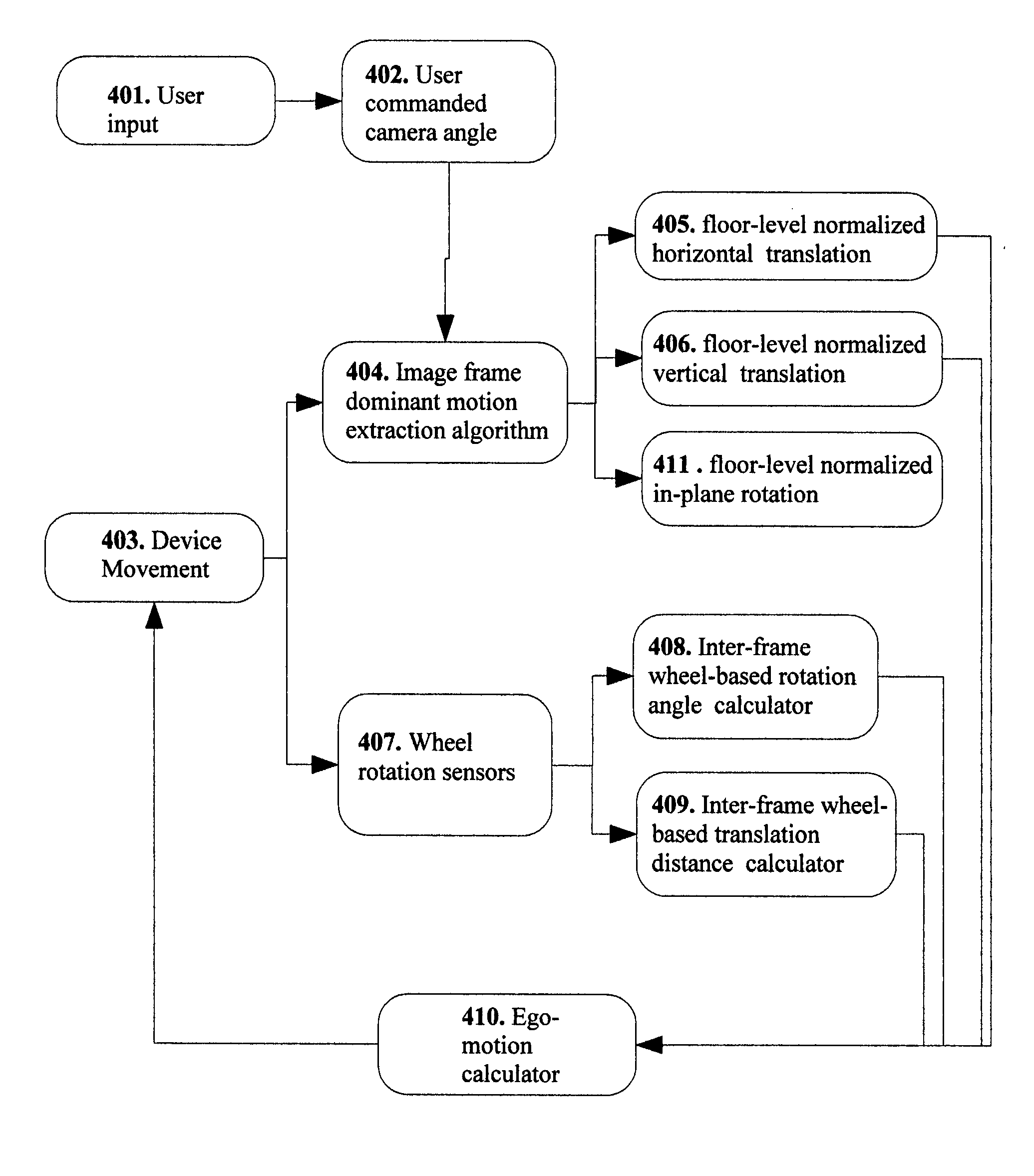
[0017]The present invention is a new and improved method and apparatus for robotic path planning, selection, and visualization.

Path-Planning Image Superposition

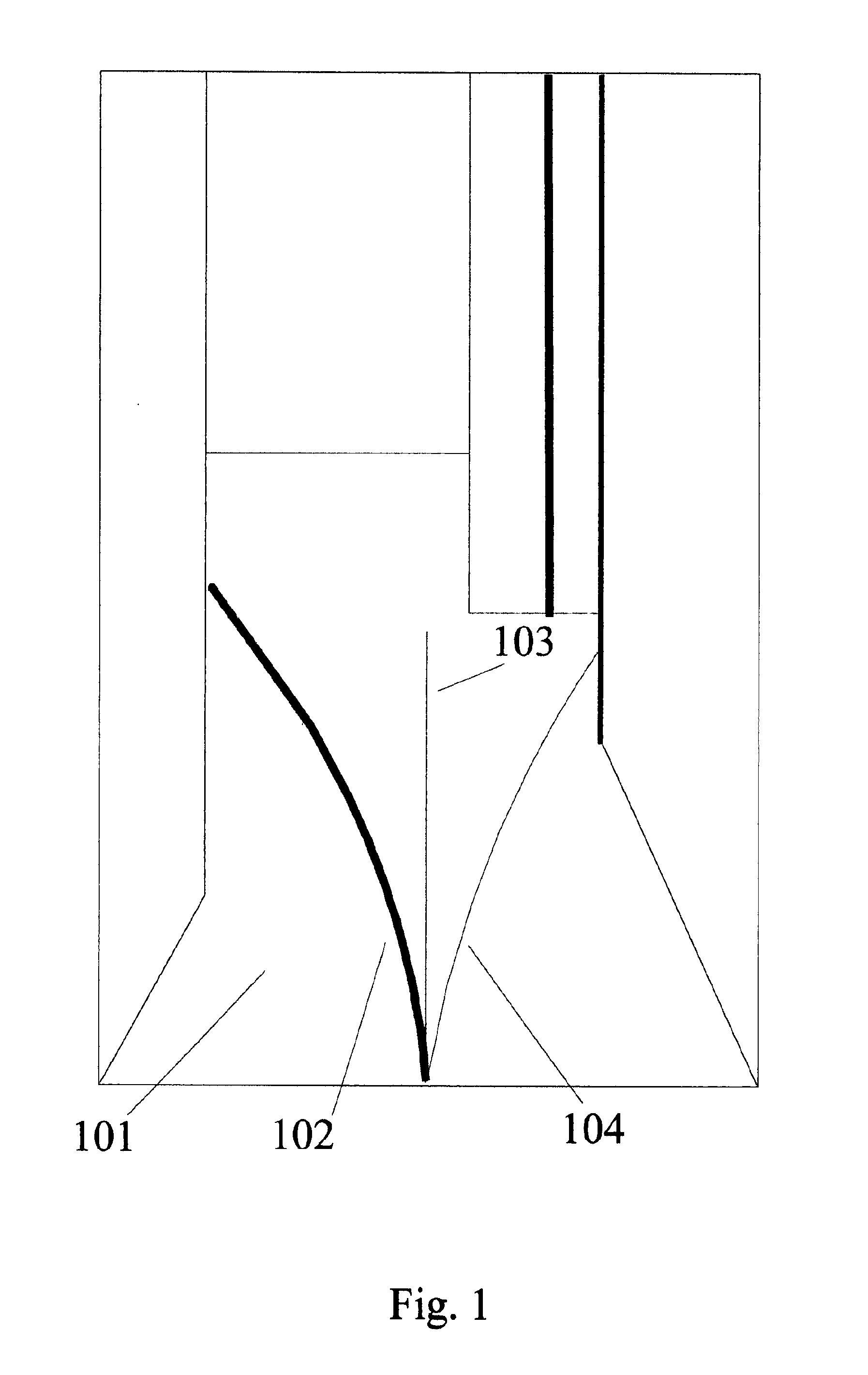
[0018]FIG. 1 is a exemplary embodiment of the invention displaying a path spline to the operator. An image of a hallway is shown to an operator 101. The operator can control a path spline 102 by using a user interface to twist it, in this case to the left. User interface techniques known in the art can control the orientation of the path spline. Alternative path splines are also shown. A straight path 103 occurs when the spline is not curved. The spline can also be made to curve to the right 104. A remotely controlled robot is programmed to move in accordance with the path the spline curve maps onto the floor. In an alternative embodiment, the path taken by the robot may be displayed as a straight line from the robot's current location to a desired destination. In yet another embodiment, the path taken by the robot is compose...


PUM


Abstract

New and Improved methods and apparatus for robotic path planning, selection, and visualization are described A path spline visually represents the current trajectory of the robot through a three dimensional space such as a room By altering a graphical representation of the trajectory—the path spline—an operator can visualize the path the robot will take, and is freed from real-time control of the robot Control of the robot is accomplished by periodically updating the path spline such that the newly updated spline represents the new desired path for the robot Also a sensor that may be located on the robot senses the presence of boundaries (obstacles) in the current environment and generates a path that circumnavigates the boundaries while still maintaining motion in the general direction selected by the operator The mathematical form of the path that circumnavigates the boundaries may be a spline

Description

BACKGROUND OF THE INVENTION[0001](1) Field of Invention[0002]The present invention is related to the field of robotics, more specifically, the invention is method and system for interactive robotic path planning, path selection, and path visualization.[0003](2) Related Art[0004]A significant pool of research has been devoted to the problem of robotic path planning—the problem of allowing an autonomous robot to navigate its way through an unfamiliar environment. However, unique problems arise when, instead of an autonomous robot, a human is controlling a remote controlled surrogate presence (henceforth referred to as a Mobile Video Teleconferencing Device, or “MVTD”).[0005]In USPTO application 20010037163 (Allard), and U.S. Pat. Nos. 6,535,793 (Allard) and 6,845,297 (Allard) a method is discussed for remote control of a mobile robot which requires the operator to select a target to move towards by means of a waypoint. This imposes a number of limitations. For example, a target must b...

Claims


Application Information

Patent Timeline
Patent Type & Authority Applications(United States)
IPC IPC(8): G06F7/00G01C21/00
CPCB25J9/1689G05B2219/35506G05B2219/40161G05D2201/0211G06T1/0014G05D1/0038G05B2219/40169
Inventor SANDBERG, ROY
Owner SANDBERG ROY
Why Eureka
Try Eureka