Skeleton type BLDC motor

a bldc motor and skeleton technology, applied in the direction of magnetic circuit rotating parts, magnetic circuit shape/form/construction, windings, etc., can solve the problems of increasing motor noise, deteriorating performance of motors which require a certain level of cogging torque, and increasing the noise of motors, so as to reduce resonance noise, reduce only the degree of cogging torque, and maintain the effect of motor performan

Inactive Publication Date: 2008-08-26
LG ELECTRONICS INC
View PDF10 Cites 8 Cited by
  • Summary
  • Abstract
  • Description
  • Claims
  • Application Information

AI Technical Summary

Benefits of technology

[0017]Therefore, an object of the present invention is to provide a BLDC motor capable of maintaining the motor performance and reducing resonance noise by reducing only higher degree of cogging torque from cogging torque generated from when the motor is driven.

Problems solved by technology

However, in the conventional skeleton type BLDC motor having such a construction, cogging torque, which is a tangential force whose tendency is to move in equilibrium with the minimum magnetic energy, is inevitably generated.
The cogging torque of higher degree becomes the main cause of resonance noise of the motor, thereby increasing noise of the motor.
In order to reduce the generation of the cogging torque, though research and development in noise reduction has been a primary focus by using a method for improving a magnetizing method of the magnet or a method for reducing the vibration source by changing a shape of the magnet, there is a problem that basic degree cogging torque as well as higher degree (the fourth degree, fifth degree, .
Thus, there is a problem that the performance of a motor which requires a certain level of cogging torque is deteriorated.

Method used


Image

  • Skeleton type BLDC motor
  • Skeleton type BLDC motor
  • Skeleton type BLDC motor

Examples


Embodiment Construction

[0032]Reference will now be made in detail to one embodiment of a rotor of a BLDC motor in accordance with the present invention, examples of which are illustrated in the accompanying drawings.

[0033]There can be a plurality of embodiments of the rotor of the BLDC motor in accordance with the present invention, of which the most preferred one will now be described.

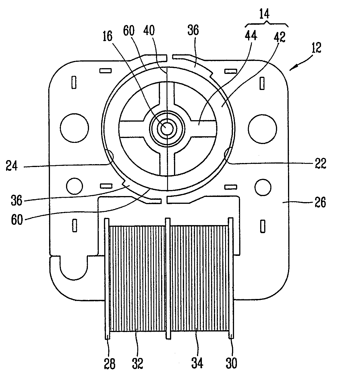
[0034]FIG. 5 is a cross-sectional view of a skeleton type BLDC motor in accordance with one embodiment of the present invention, and FIG. 6 is a cross-sectional view taken along line VI-VI of FIG. 5.

[0035]The BLDC motor of the present invention includes: a motor housing 1; a stator 12 which is fixed to the inside of the motor housing 10 and to which the power is applied; a rotor 14 disposed at an inner circumferential surface of the stator 12 with an air gap and rotated by interlocking with the stator 12; and a rotary shaft 16 mounted at the center of the rotor 14 and rotated together with the rotor 14, for transferring a r...


PUM


Abstract

A rotor of a BLDC motor includes: a rotor divided into a north pole and a south pole on the basis of a magnetic pole separating line; and a stator at which the rotor is disposed with an air gap, the stator having a first pole shoe, a second pole shoe and a pair of detent grooves at its inner surface, wherein an air gap forming portion for enlarging an air gap between the rotor and the detent grooves is formed at both end portions of the rotor where the magnetic pole separating line passes, so that the rotor can maintain the motor performance and reduce resonance noise by reducing only higher degree of cogging torque from cogging torque generated when the motor is driven.

Description

BACKGROUND OF THE INVENTION[0001]1. Field of the Invention[0002]The present invention relates to a skeleton type BLDC motor, and more particularly, to a BLDC motor which reduces resonance noise by reducing cogging torque.[0003]2. Description of the Background Art[0004]FIG. 1 is a perspective view of a skeleton type BLDC motor in accordance with the conventional art, FIG. 2 is a cross-sectional view of a skeleton type BLDC motor in accordance with the conventional art; and FIG. 3 is a cross-sectional view taken along line III-III of FIG. 2.[0005]The conventional BLDC motor is made up of a stator 102 to which the power is applied; a rotor 104 disposed at an inner circumferential surface of the stator 102 with an air gap and rotated by interlocking with the stator 102; and a rotary shaft 106 mounted at the center of the rotor 104 and rotated together with the rotor 104, for transferring a rotary force to the outside.[0006]A PCB 108 having a driver circuit for driving the rotor 104 ther...

Claims


Application Information

Patent Timeline
Patent Type & Authority Patents(United States)
IPC IPC(8): H02K37/16H02K21/18
CPCH02K29/03
Inventor LEE, HO-JAELEE, DONG-ILSHIN, HYOUN-JEONG
Owner LG ELECTRONICS INC
Why Eureka
Try Eureka