Method and implant device for grafting adjacent vertebral bodies

a technology for grafting and adjacent vertebrae, which is applied in the field of vertebral implant devices, can solve the problems of limited insertion instruments, limited surgery flexibility, and large bulky all-in-one construction of conventional graft devices used in corpectomy procedures, and achieves minimally invasive approaches, convenient assembly and insertion, and enhanced surgery flexibility

Active Publication Date: 2016-12-08
GLOBUS MEDICAL INC
View PDF2 Cites 8 Cited by
  • Summary
  • Abstract
  • Description
  • Claims
  • Application Information

AI Technical Summary

Benefits of technology

The present invention provides an improved implant device that is modular, flexible, and easy to assemble. It can be inserted from a lateral or lateral extracavity approach and facilitates bone grafting. The device includes a bristle post to support bone growth and strong and stable endplate gripping. It also provides modular in situ insertion, larger endplates, a snap-in ball-joint rod, a snap-on bristle cage, and a snap-on allograft strut. The device enables motion preservation and is suitable for minimally invasive surgeries.

Problems solved by technology

While these conventional devices may generally provide adequate results, they have several disadvantages.
For example, conventional graft devices utilized in a corpectomy procedure typically have a relatively bulky all-in-one construction and include several components.
Such an implant construction limits surgery flexibility, including the approach to the spine.
The instrument utilized for insertion is likewise limited due to the constraints of existing implant devices.

Method used


Image

  • Method and implant device for grafting adjacent vertebral bodies
  • Method and implant device for grafting adjacent vertebral bodies
  • Method and implant device for grafting adjacent vertebral bodies

Examples


Embodiment Construction

[0038]The following description of the preferred embodiment(s) is merely exemplary in nature and is in no way intended to limit the invention, its application, or uses.

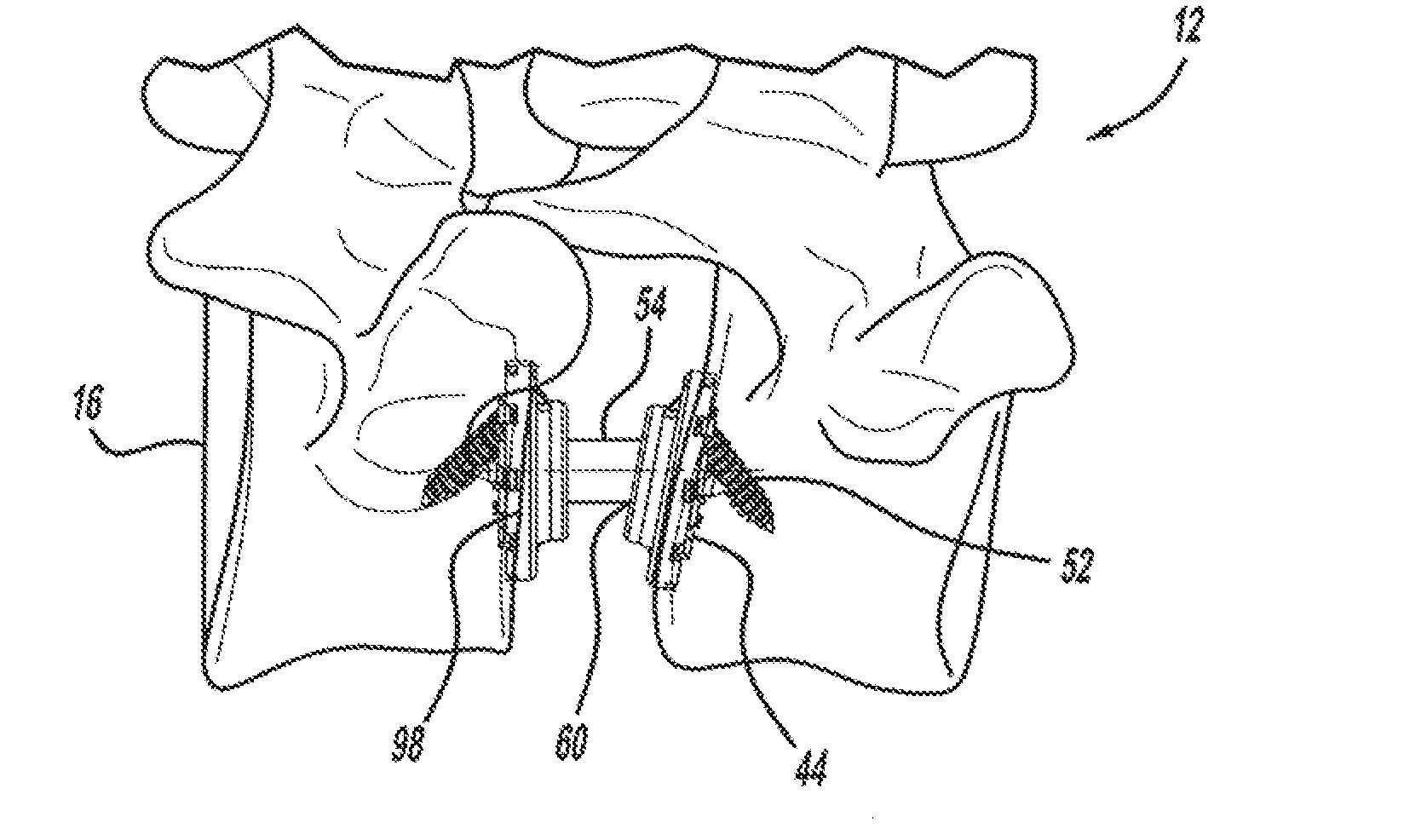
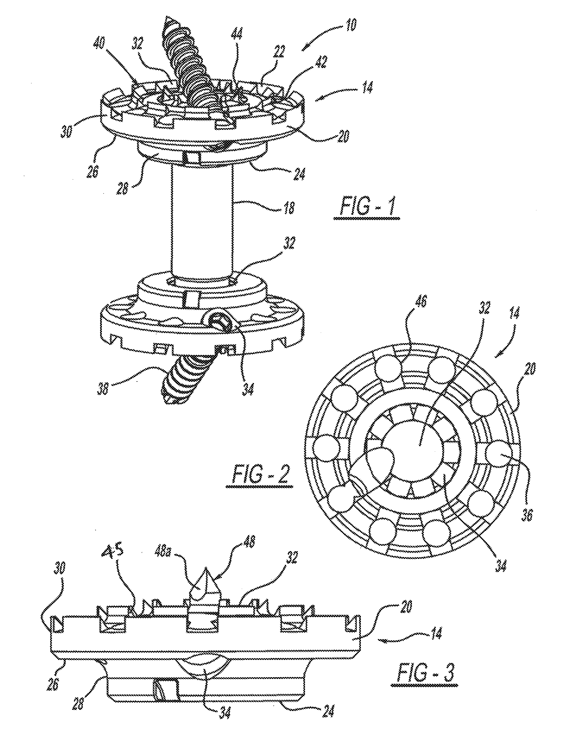
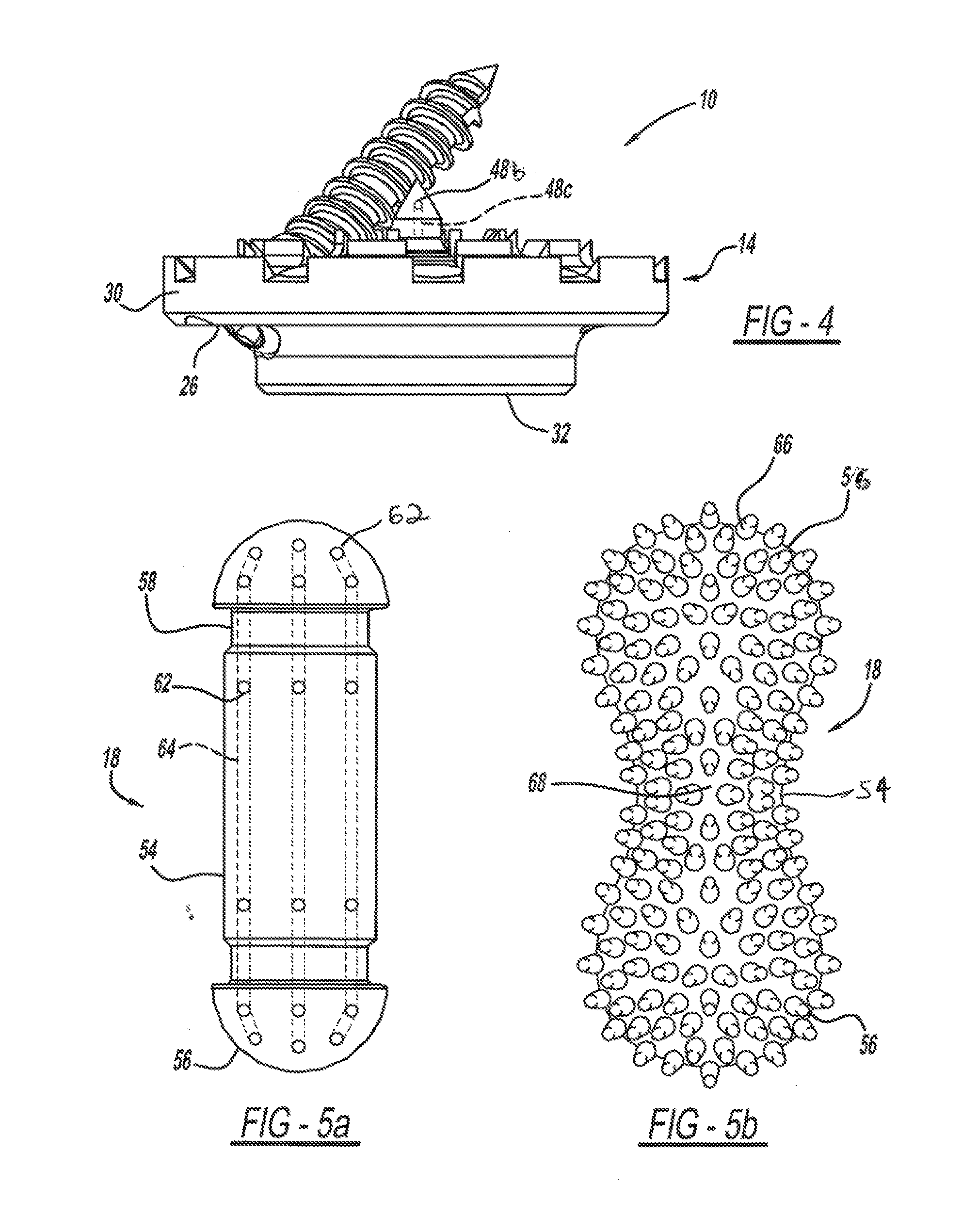
[0039]Referring to FIGS. 1-20, an implant device 10 for use between adjacent bone structures is shown. In this example, the implant device 10 is a vertebral implant device 10 designed to be implanted in regions of the spine 12, such as the cervical, thoracic, and lumbar spine, although the location of implantation is non-limiting. For example, the vertebral implant device 10 can be used in the lateral extracavity, anterolateral, or direct anterior regions of the thoracolumbar spine to address indications relating to trauma, tumors, and degenerative issues such as scoliosis, or the like. The vertebral implant device 10 may serve as a modular mechanical graft to support eventual bone growth. The vertebral implant device 10 and its individual components can be fabricated from various materials, such as, plastic, metal, a...


PUM


Abstract

A methodology for grafting together adjacent bony structures is provided using an implant device having an endplate with an inner disc portion and outer ring portion spaced from the inner disc portion by a connecting wall disposed there between. An endplate interior surface includes a retaining structure for securing the endplate to one of the bony structures, and endplate an exterior surface has an integrally formed socket. A ball-joint rod has a longitudinally extending body and an end, and at least a portion of the ball-joint rod end is curvilinear in shape. The curvilinear ball-joint rod end is rotatably disposed in the endplate socket to fixedly interconnect the bony structures.

Description

CROSS-REFERENCE TO RELATED APPLICATIONS[0001]This application is a divisional of U.S. patent application Ser. No. 13 / 866,512, filed Apr. 19, 2013, which is a continuation-in-part of U.S. patent application Ser. No. 13 / 366,890, filed Feb. 6, 2012, now U.S. Pat. No. 8,425,606, which claims the benefit of U.S. Provisional Application No. 61 / 499,271, filed on Jun. 21, 2011, the contents of which are hereby incorporated by reference in their entireties for all purposes.BACKGROUND OF THE INVENTION[0002]1. Field of the Invention[0003]The present disclosure relates generally to a vertebral implant device, and more particularly, to a method and implant device for grafting together adjacent vertebral bodies.[0004]2. Description of Related Art[0005]Diseases and injury to bone structures, such as the vertebral column, and conditions requiring surgical intervention are relatively common. A variety of conventional implant or graft devices are presently available for use in specific areas. The dev...

Claims


Application Information

Patent Timeline
Patent Type & Authority Applications(United States)
IPC IPC(8): A61F2/44A61F2/28A61F2/46
CPCA61F2/4465A61F2/4425A61F2/4611A61F2/2846A61F2002/443A61F2002/285A61F2310/00023A61F2220/0016A61F2002/30225A61F2002/30604A61F2002/30662A61F2002/30507A61F2002/30665A61F2002/2835A61F2002/30062A61F2002/30224A61F2002/30227A61F2002/30233A61F2002/30574A61F2002/30576A61F2002/30578A61F2002/30607A61F2002/30616A61F2002/3065A61F2002/30663A61F2002/30729A61F2002/30777A61F2002/30779A61F2002/30785A61F2002/30787A61F2002/30789A61F2002/30825A61F2002/30841A61F2002/30863A61F2002/30884A61F2002/30891A61F2002/30894A61F2002/30492A61F2002/3055A61F2002/30235A61F2002/30433A61F2002/305A61F2002/30845A61F2002/30593A61F2/4455
Inventor COWAN, JOHN A.
Owner GLOBUS MEDICAL INC
Why Eureka
Try Eureka