Locomotive performance testing apparatus

a technology for testing apparatus and locomotion, applied in the direction of instruments, structural/machine measurement, gymnastics exercise, etc., can solve the problem of unsatisfactory test and achieve the effect of stably performing the locomotive performance of the robo

Active Publication Date: 2011-12-27
HONDA MOTOR CO LTD
View PDF7 Cites 6 Cited by
  • Summary
  • Abstract
  • Description
  • Claims
  • Application Information

AI Technical Summary

Benefits of technology

[0011]According to the locomotive performance testing apparatus of the second aspect of the present invention, the driving velocity of the endless belt is controlled so as to enclose the desired ZMP in the stable support area (an enclosed area contacted by a foot portion of the leg of the robot is planar and has no recessed portion in shape). Thereby, the locomotive performance of the robot can be performed by avoiding such situation that the posture of the robot becomes unstable because of the deviation of the desired ZMP from the stable support area due to the motion alteration or the like of the robot.
[0013]According to the locomotive performance testing apparatus of the third aspect of the present invention, the alteration pattern of the driving velocity of the endless belt is controlled to have a phase difference relative to the alteration pattern of the moving velocity of the robot whose locomotive performance is tested on the endless belt. Here, the term “phase difference” refers to a factor for determining a temporal deviation between the driving velocity alteration of the endless belt and the moving velocity alteration of the robot. For example, according to the signs of the phase difference, it may be determined whether the driving velocity of the endless belt is changing faster or slower than the moving velocity of the robot. Moreover, according to the magnitude of the phase difference, it may be determined how much the deviation would be between the driving velocity of the endless belt and the moving velocity of the robot. Thereby, the motion tempos of the endless belt and the robot can be maintained in harmony in relation to the phase difference.
[0017]According to the locomotive performance testing apparatus of the fifth aspect of the present invention, the robot may be configured to control the walking motions or running motions thereof so as to enclose the desired ZMP of the robot in the stable support area. Thereby, the locomotive performance of the robot can be performed by avoiding such situation that the posture of the robot becomes unstable because of the deviation of the desired ZMP from the stable support area due to the driving velocity alteration or the like of the endless belt.
[0025]According to the locomotive performance testing apparatus of the ninth aspect of the present invention, the robot motion plan is made on the basis of the motor working plan. The motions of the robot are controlled according to the robot motion plan. Thereby, the alteration pattern of the moving velocity of the robot whose locomotive performance is tested on the endless belt can be controlled in relation to the alteration pattern of the driving velocity of the endless belt. As a result, the motion tempo of the endless belt and the motion tempo of the robot can be harmonized so as to make the motion tempo of the robot come to a compromise with the motion tempo of the endless belt, allowing the locomotive performance of the robot to be performed stably.

Problems solved by technology

However, when locomotive performance of a legged robot is tested by using a treadmill, a satisfactory test may not be performed if a motion rhythm or tempo of the treadmill is not in harmony with that of the robot.

Method used


Image

  • Locomotive performance testing apparatus
  • Locomotive performance testing apparatus
  • Locomotive performance testing apparatus

Examples


Embodiment Construction

[0033]Hereinafter, embodiments of a locomotive performance testing apparatus according to the present invention will be described with reference to the drawings.

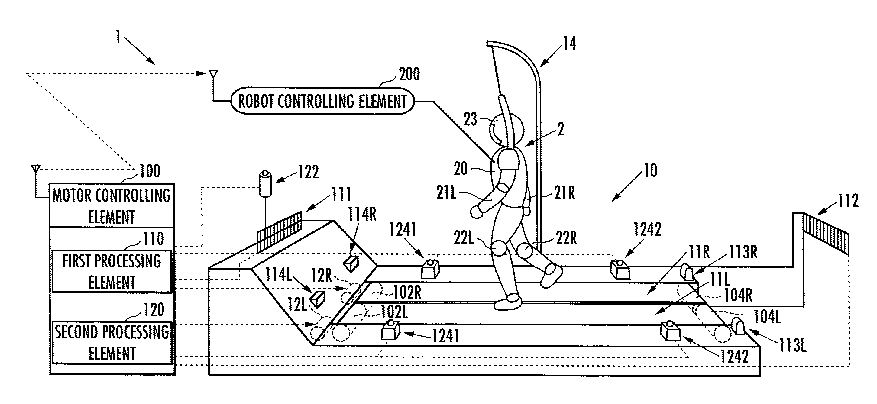
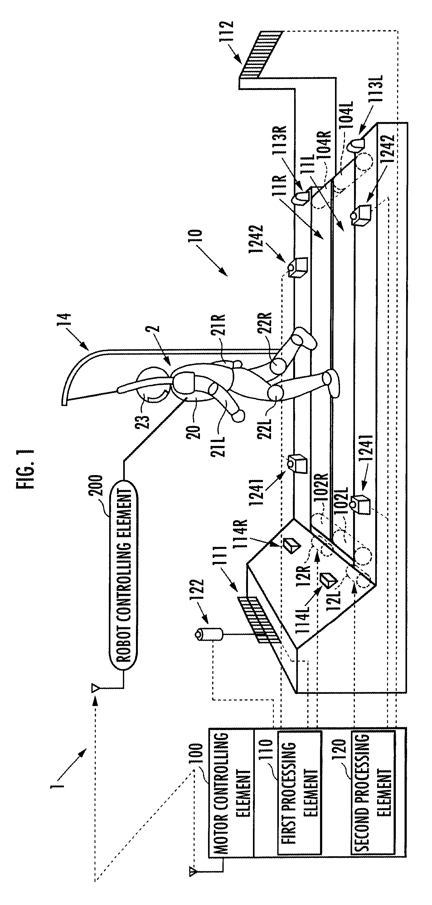
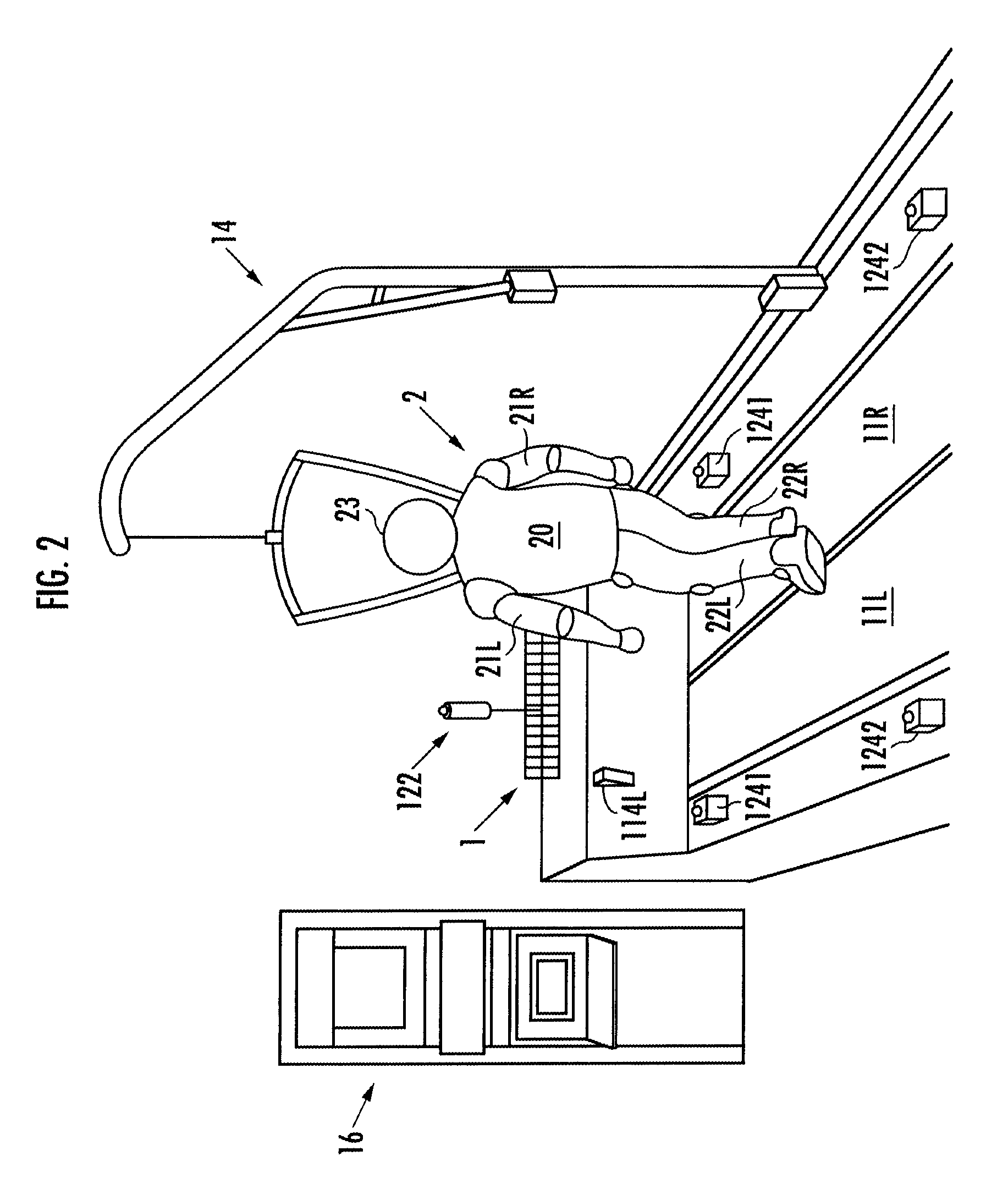
[0034]First, the configuration of the locomotive performance testing apparatus will be explained with reference to FIG. 1 and FIG. 2. Hereinafter, numerals L and R are used to denote the left and right components, respectively. However, if the left component and the right component are common or the left and right components are mentioned as a whole, the numerals will be omitted where appropriate.

[0035]The locomotive performance testing apparatus 1 is used to test the locomotive performance of a robot 2 or the like, including a treadmill 10, a monitor which displays the locomotive performance of the robot 2 or other measuring devices 16 (refer to FIG. 2), and a motor controlling element 100.

[0036]The treadmill 10 includes a pair of endless belts 11L and 11R which are disposed in parallel, two motors 12L and 12R which drive t...


PUM

PropertyMeasurementUnit
velocityaaaaaaaaaa
driving velocityaaaaaaaaaa
moving velocityaaaaaaaaaa

Abstract

Provided is a testing apparatus capable of testing locomotive performance of a robot while harmonizing motions of the apparatus with that of the robot. According to the locomotive performance testing apparatus (1), a motor working plan is made on the basis of a robot motion plan, and a motor (12) is driven according to the motor working plan. As a result, an alteration pattern of a driving velocity of an endless belt (11) can be controlled according to an alteration pattern of a moving velocity of a robot (2) whose locomotive performance is being tested on the endless belt (11). Moreover, a motion tempo of the endless belt (11) and a motion tempo of the robot (2) are so harmonized that the former tempo may approach the latter tempo, and the locomotive performance of the robot (2) can be stably tested in that state.

Description

PRIORITY CLAIM[0001]The present application is based on and claims the priority benefit of Japanese Patent Application 2006-297723 filed on Nov. 1, 2006, the contents of which are incorporated herein by reference in its entirety.BACKGROUND OF THE INVENTION[0002]1. Field of the Invention[0003]The present invention relates to a locomotive performance testing apparatus configured to test locomotive performance of a robot capable of moving according to motions of a plurality of legs.[0004]2. Description of the Related Art[0005]There has been disclosed a treadmill configured to adjust a driving velocity of an endless belt driven by a motor according to an anteroposterior position of a runner trained on the endless belt for walking or running (for example, refer to paragraphs 0010 to 0014 and FIG. 3 in Japanese Patent Laid-open No. H07-136295, and paragraphs 0005 to 0007 and FIG. 1 in Japanese Patent Laid-open No. H10-071216).[0006]However, when locomotive performance of a legged robot is...

Claims


Application Information

Patent Timeline
Patent Type & Authority Patents(United States)
IPC IPC(8): G01N19/00G01M99/00
CPCG01M99/005G01M99/008A63B22/0235A63B22/0242A63B2022/0292A63B2024/0093A63B2220/13A63B2220/30A63B22/0292B25J19/0095Y10S901/01
Inventor UDONO, KENRO
Owner HONDA MOTOR CO LTD
Why Eureka
Try Eureka