
Simple method for calculating camera defocus from an image scene

a simple method and image scene technology, applied in the field of image generation, can solve problems such as focal gradients

Active Publication Date: 2007-09-20
SONY CORP +1
View PDF39 Cites 206 Cited by
  • Summary
  • Abstract
  • Description
  • Claims
  • Application Information

AI Technical Summary

Problems solved by technology

Determining the distance between objects in a three dimensional spatial scene is an important problem in, but not limited to, auto-focusing digital and video cameras, computer / robotic vision and surveillance.
A limited depth of field inherent in most camera systems causes the focal gradient.

Method used


Image

  • Simple method for calculating camera defocus from an image scene
  • Simple method for calculating camera defocus from an image scene
  • Simple method for calculating camera defocus from an image scene

Examples


Embodiment Construction

[0034] In the following detailed description of embodiments of the invention, reference is made to the accompanying drawings in which like references indicate similar elements, and in which is shown by way of illustration specific embodiments in which the invention may be practiced. These embodiments are described in sufficient detail to enable those skilled in the art to practice the invention, and it is to be understood that other embodiments may be utilized and that logical, mechanical, electrical, functional, and other changes may be made without departing from the scope of the present invention. The following detailed description is, therefore, not to be taken in a limiting sense, and the scope of the present invention is defined only by the appended claims.

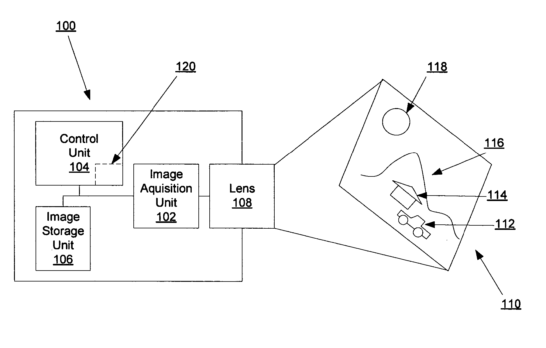
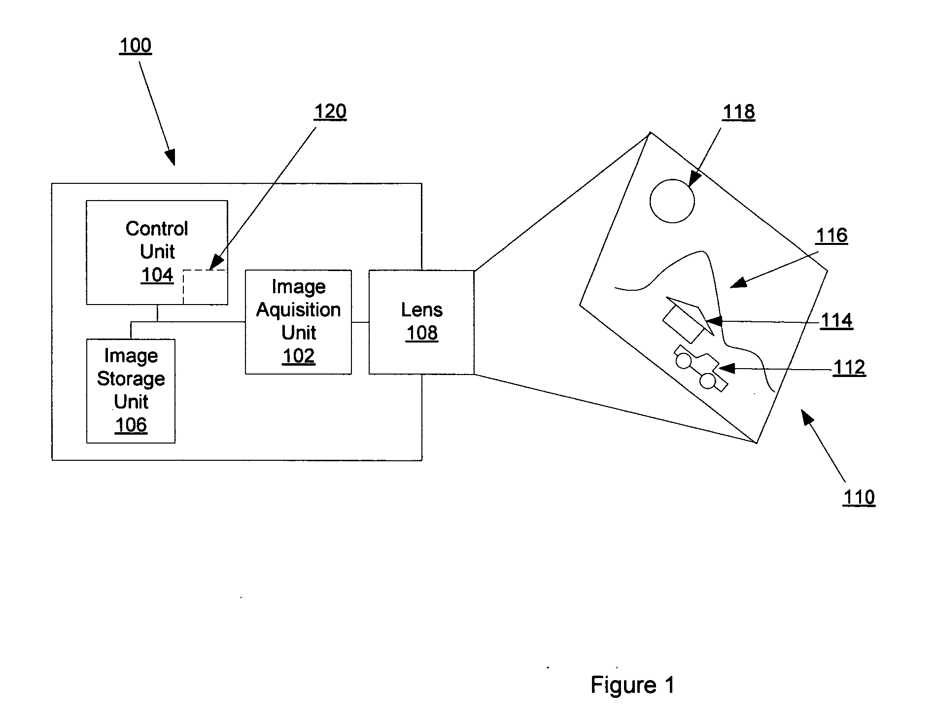
[0035]FIG. 1 illustrates one embodiment of an imaging system 100 that captures an image of a three dimensional spatial scene 110. References to an image or a picture are to an image of a three dimensional scene captured by ...


PUM


Abstract

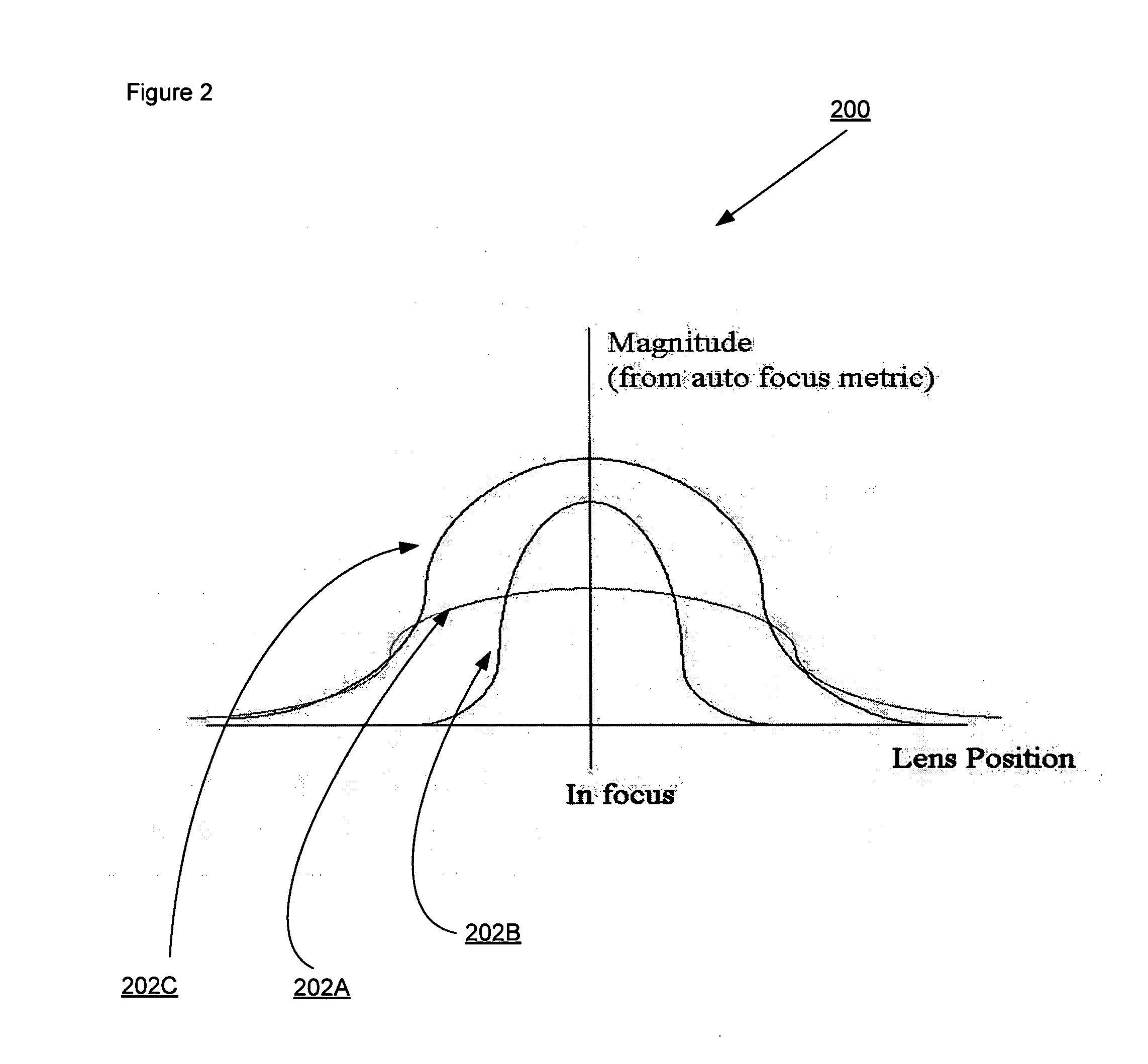
An imaging acquisition system that generates a picture depth from an auto focus curve generated from picture of a three dimensional spatial scene is described. The auto focus curve comprises a step edge. The system generates the depth based on the step edge and a reference auto focus normalization curve.

Description

RELATED APPLICATIONS [0001] This patent application is related to the co-pending U.S. patent application, entitled A NEW METHOD FOR CREATING A DEPTH MAP FOR AUTO FOCUS USING AN ALL IN FOCUS PICTURE AND 2D SCALE SPACE MATCHING, Ser. No. 11 / 185,611 and DEPTH INFORMATION FOR AUTO FOCUS USING TWO PICTURES AND TWO-DIMENSIONAL GAUSSIAN SCALE SPACE THEORY, Ser. No. 11 / 204,942.FIELD OF THE INVENTION [0002] This invention relates generally to imaging, and more particularly to generating a depth map from a single image. COPYRIGHT NOTICE / PERMISSION [0003] A portion of the disclosure of this patent document contains material which is subject to copyright protection. The copyright owner has no objection to the facsimile reproduction by anyone of the patent document or the patent disclosure as it appears in the Patent and Trademark Office patent file or records, but otherwise reserves all copyright rights whatsoever. The following notice applies to the software and data as described below and in ...

Claims


Application Information

Patent Timeline
Patent Type & Authority Applications(United States)
IPC IPC(8): H04N13/02
CPCH04N5/23212H04N23/673
Inventor WONG, EARL QUONGKUSHIDA, HIDENORINAKAMURA, MAKIBI
Owner SONY CORP
Learn More