Multilayer electric connector

a multi-layer, electric connector technology, applied in the direction of coupling contact members, coupling device connections, coupling devices, etc., can solve the problems of insufficient space to allow more flexible circuit layout and more effective heat radiation, and achieve the effect of enhancing signal quality and sufficient room

Inactive Publication Date: 2005-12-20
LIEN TEH SOU
View PDF9 Cites 17 Cited by
  • Summary
  • Abstract
  • Description
  • Claims
  • Application Information

AI Technical Summary

Benefits of technology

[0003]Accordingly, the present invention is to provide a multilayer electric connector having sufficient room for housing filtering electronic elements and for effective heat radiation. A multilayer electric connector therefore designed comprises a main board having at least two layers of slots, each upper slot and lower slot sandwiched by two lateral circuit boards. Two conductive sets electrically connect the upper slot, lower slot and those two circuit boards. The upper conductive set has two conductive members, one of which connects the main board via the upper slot and the right circuit board, the other of which connects the right circuit board and an external instrument terminal. The lower conductive set connects the lower slot and the left circuit board in a symmetric configuration as the upper conductive set connects the upper slot and the right circuit board. The circuit boards, coupled with the conductive sets, form two receptacles therebetween. Thereby, sufficient room is produced between two layers of slots for housing electronic elements that enhance signal quality by filtering or converting mechanisms.

Problems solved by technology

Later on, another multilayer electric connector disclosed by R.O.C. Pat. No. 510604 has housing space for a filtering module, but the space does not suffice to allow more flexible circuit layouts and more effective heat radiation.

Method used


Image

  • Multilayer electric connector
  • Multilayer electric connector
  • Multilayer electric connector

Examples


Embodiment Construction

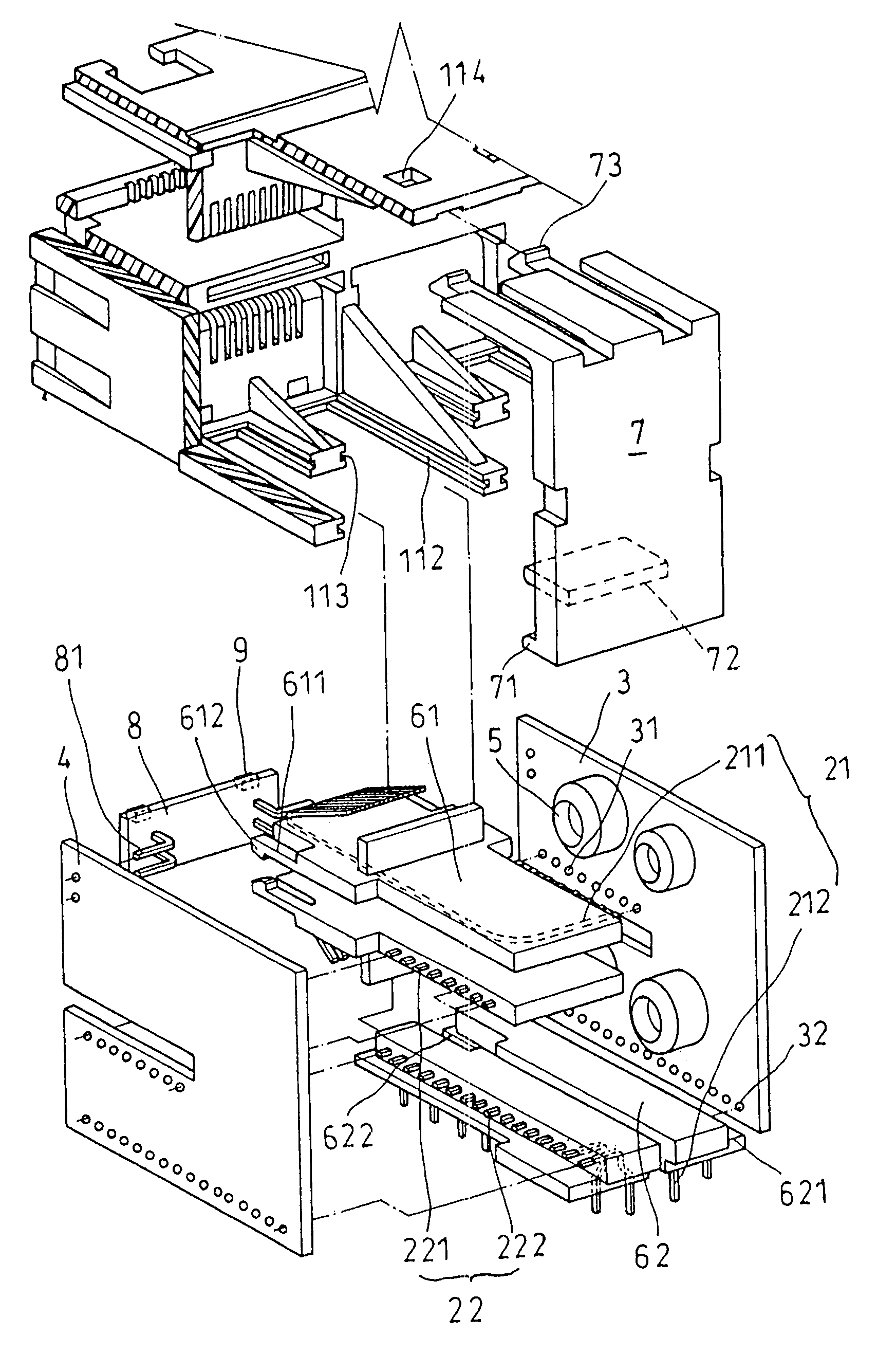
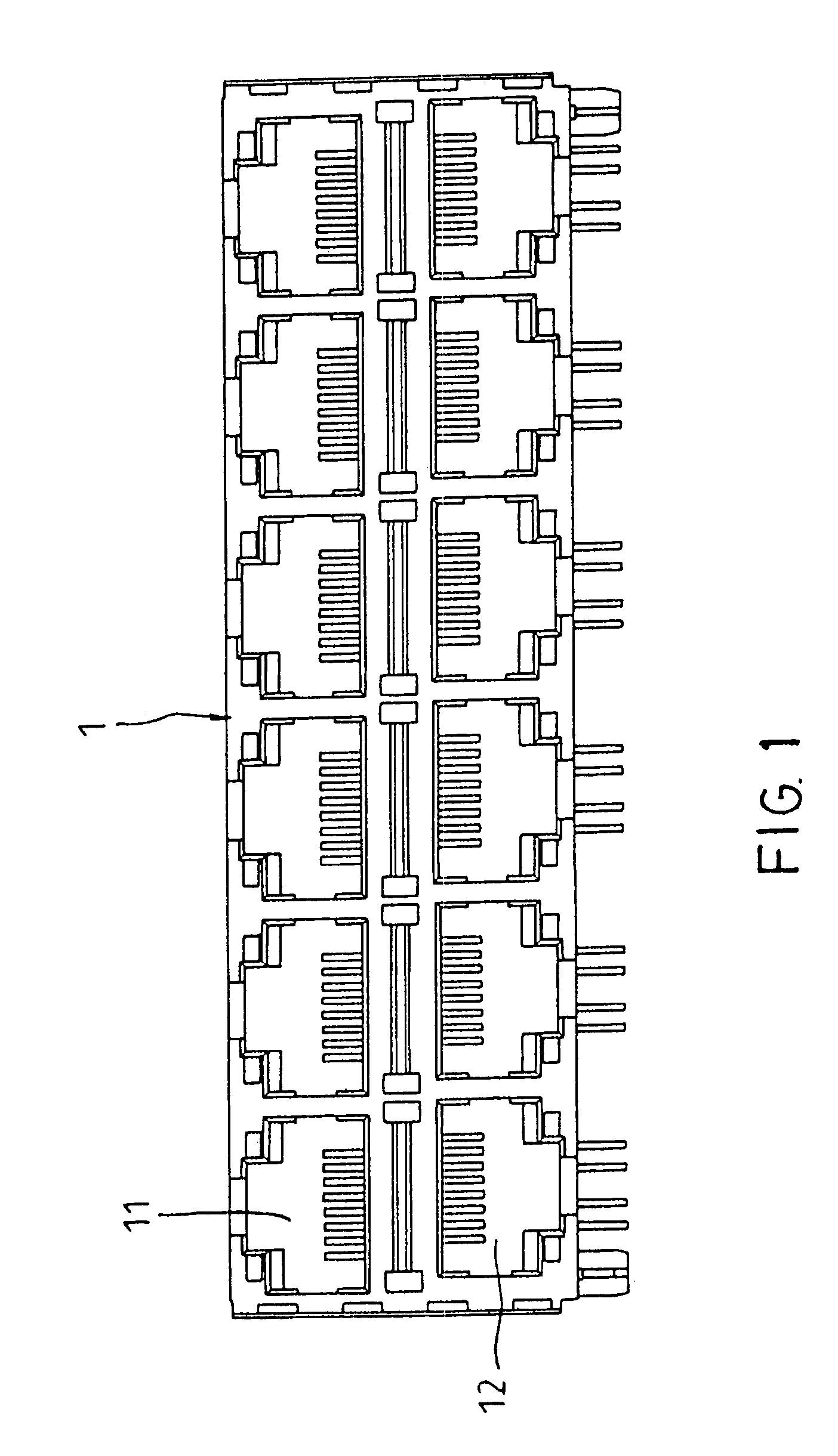
[0010]As shown in FIG. 1, a preferred embodiment of the present invention as a multilayer electric connector comprises a main board 1 that has a plurality of slots (11, 12, for example). To save space, those slots are arranged in an interlaced fashion into different layers so that external connectors can be inserted or pulled out easily; in this the preferred embodiment, there are two layers.

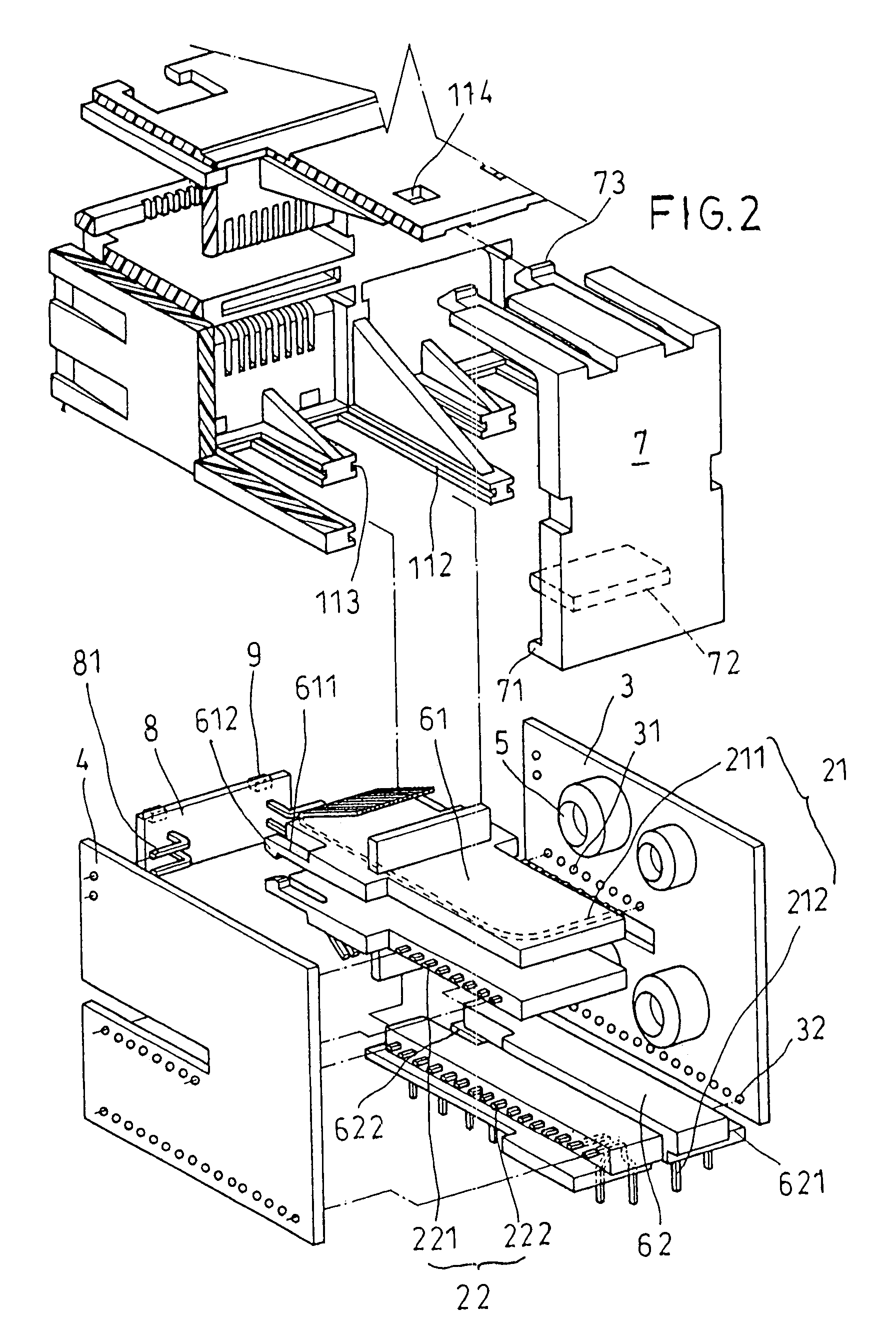
[0011]As shown in FIGS. 2, 3 and 4, the multilayer electric connector further includes a plurality of conductive sets each to couple with a respective upper slot 11 and a respect lower slot 12. In this present invention having two layers of slots, the conductive sets are categorized into upper conductive sets and lower conductive sets. Each of an upper conductive set 21 and a lower conductive set 22 has a first conductive member (211, 221) and a second conductive member (212, 222). The first conductive member 211 of the upper conductive set 21 has one terminal for electrically connecting to the ...


PUM


Abstract

A multilayer electric connector comprises a main board having at least two layers of slots, each upper slot and lower slot sandwiched by two-lateral circuit boards. Two conductive sets electrically connect the upper slot, lower slot and those two circuit boards. The upper conductive set has two conductive members, one of which connects the main board via the upper slot and the right circuit board, the other of which connects the right circuit board and an external instrument terminal. The lower conductive set connects the lower slot and the left circuit board in a symmetric configuration as the upper conductive set connects the upper slot and the right circuit board. The circuit boards, coupled with the conductive sets, form two receptacles therebetween.

Description

FIELD OF INVENTION[0001]The present invention relates to multilayer electric connectors, more particularly to a multilayer electric connector in which conductive components are assembled in three-dimensional configuration, thereby producing a larger space for housing electronic elements for enhancing signal quality by filtering or converting mechanisms.DESCRIPTION OF THE PRIOR ART[0002]The twenty-first century is an age of telecommunication when communication hardware is becoming more and more complex, which requires better quality of signal transmission. The present electric connectors for signal transmission are RJ type connectors. To increase instrument capacity that can be supported by an electric connectors multilayer electric connectors such as the one disclosed by R.O.C. Pat. No. 483606 is introduced to mate a plurality of input / output terminals. This invention is disadvantageous in a lack of a filtering mechanism for reducing high-frequency noises induced in the connector. L...

Claims


Application Information

Patent Timeline
Patent Type & Authority Patents(United States)
IPC IPC(8): H01R13/514
CPCH01R13/514H01R24/64
Inventor LIEN, TEH SOU
Owner LIEN TEH SOU
Why Eureka
Try Eureka