Method for feedback controlled electrospray
a technology of electrospray and feedback, which is applied in the direction of particle separator tube details, instruments, separation processes, etc., can solve the problems of ion current, fixed or difficult adjustment of one or more of the foregoing parameters, and the use of both foregoing methods,
- Summary
- Abstract
- Description
- Claims
- Application Information
AI Technical Summary
Benefits of technology
Problems solved by technology
Method used
Image
Examples
example 1
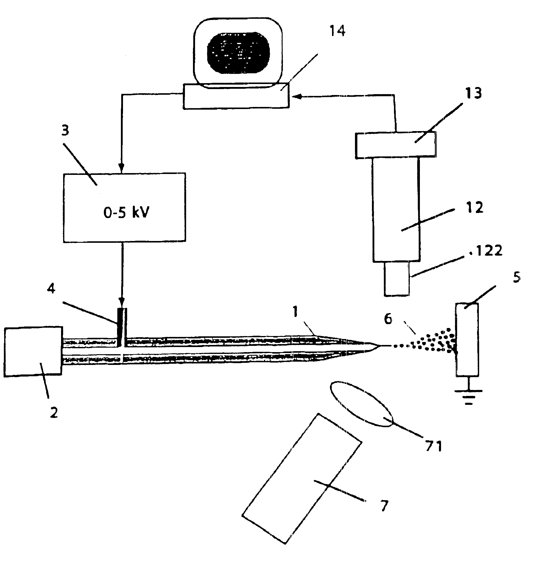
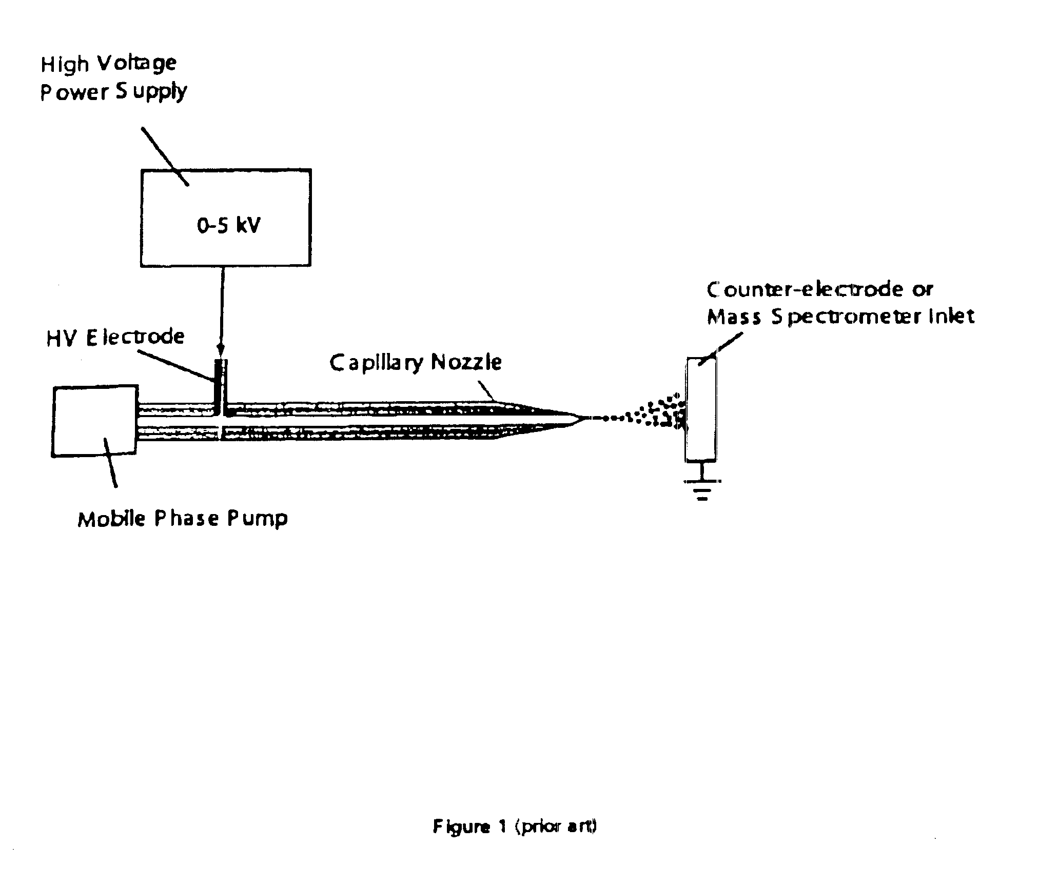
[0098]A tapered, metal coated fused-silica capillary nozzle, fabricated from 360 μm OD×75 μm ID tubing and having a 30 μm OD tip, was connected to a syringe pump delivering mobile phase (aqueous solution of 50% Methanol, 2% Acetic Acid) at a flow rate between 100 nL / min to 2 μL / min. The output (0-5 kV) of a computer controlled high voltage (HV) power supply was connected to the metal coating on the nozzle. The nozzle was positioned perpendicular to a 1 cm diameter metal “ground plate” connected to ground potential. The distance between the plate and capillary nozzle was adjustable between 1 to 20 mm.
[0099]A CCD camera based microscope (magnification approx. 100×) was positioned above the capillary nozzle to provide an image of the capillary nozzle and resultant aerosol plume. The output of the CCD camera was connected to an image acquisition card resident within the same computer controlling the HV power supply. Below the capillary nozzle, and at an angle of approximately 20 degrees...
example 2
[0105]The apparatus of example 1 was modified so that the syringe pump was replaced with a gradient liquid chromatography (LC) system. This system enabled the mobile phase composition to be varied during the course of the run. Solvent A consisted of an aqueous solution of 10% acetonitrile and 0.1% formic acid. Solvent B consisted of an aqueous solution of 90% acetonitrile and 0.1% formic acid. The liquid chromatography system could adjust the mobile phase composition to be any combination of the two solvents, and could create a linear gradient in composition from solvent A to B in any time scale between 1 and 300 minutes.
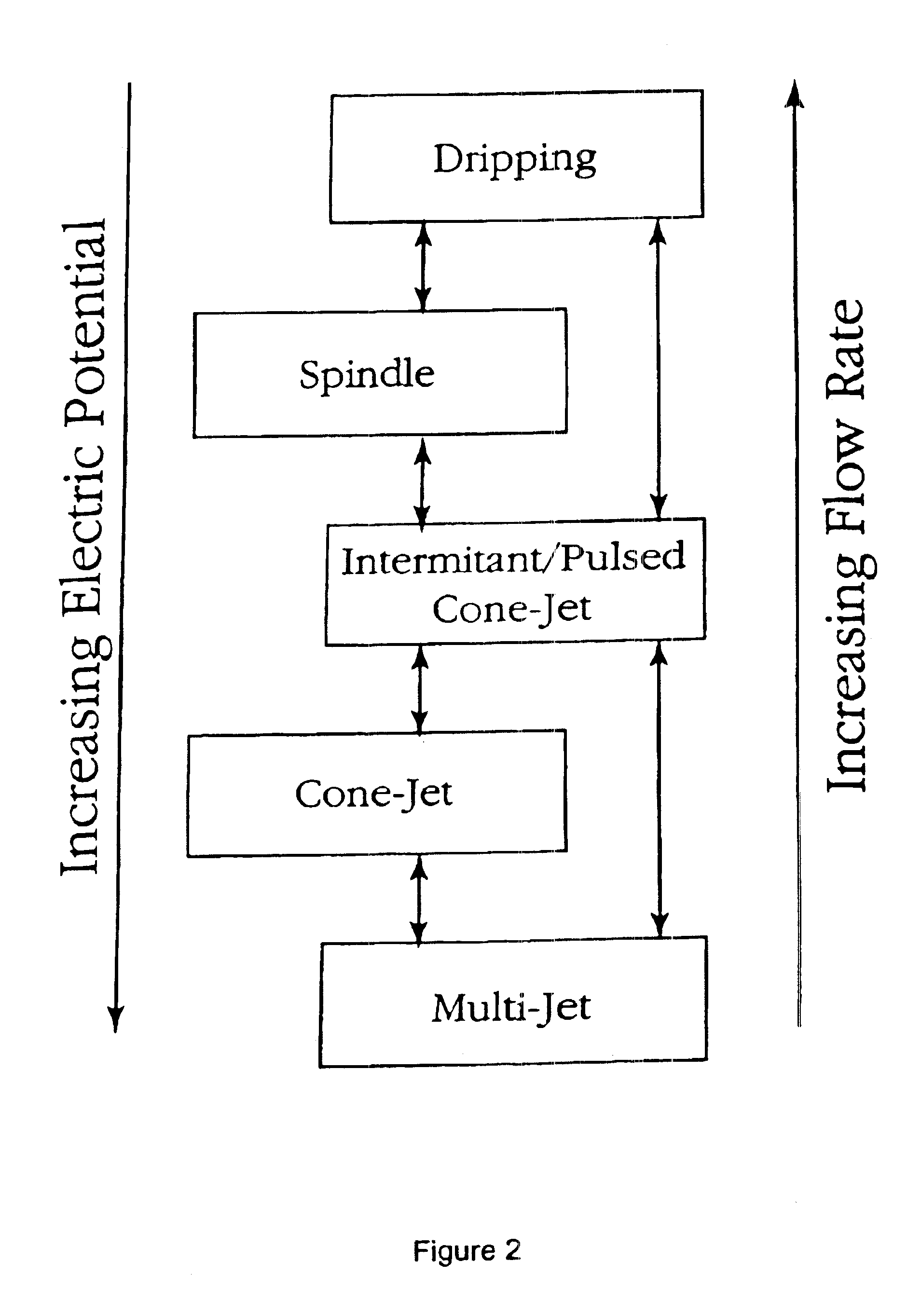
[0106]The flow rate was kept constant at 500 nL / min and the LC system was set to deliver solvent A. The computer control system was initialized and a stable cone-jet mode was established and maintained at 2100 V. The composition of the mobile phase was changed in a linear fashion to solvent B over the course of 10 minutes. As the mobile phase changed in composition ...
example 3
Variation 6
[0141]The apparatus of variation 5 could be modified so that a split, or segmented, photodiode would replace the two discrete photodiodes. The co-localization of the photodiodes would improve the common mode rejection response and would further reduce noise inherent to the light source.
Hybrid Control System
[0142]Each of the previously described general systems for static and dynamic control have limitations that are particularly well addressed by combining elements of each independent system. Put another way, each system has advantages that complement each other well.
[0143]The static control system and the dynamic control system each offer advantages not found in the other. Thus, the static control system is better suited for use with stable cone-jet forms of electrospray than the dynamic control system, since such modes generate little if any frequency information upon which the dynamic control system could act. On the other hand, the dynamic control system is very well ...
PUM
 Abstract
Description
Claims
Application Information
 - R&D
- Intellectual Property
- Life Sciences
- Materials
- Tech Scout
- Unparalleled Data Quality
- Higher Quality Content
- 60% Fewer Hallucinations
Browse by: Latest US Patents, China's latest patents, Technical Efficacy Thesaurus, Application Domain, Technology Topic, Popular Technical Reports.
© 2025 PatSnap. All rights reserved.Legal|Privacy policy|Modern Slavery Act Transparency Statement|Sitemap|About US| Contact US: help@patsnap.com


