Apparatus and method for driving circuit elements based on groups of instruction values

a technology of instruction value and circuit element, applied in the direction of digital signal error detection/correction, instruments, recording signal processing, etc., can solve the problem of reducing the maximum voltage that can be applied to those coils to a half disadvantageously, shortening the thrust on the lens being driven in the focus direction, and reducing the number of interconnection wires. the effect of the number of wires

Inactive Publication Date: 2005-12-20
PANASONIC CORP
View PDF10 Cites 1 Cited by
  • Summary
  • Abstract
  • Description
  • Claims
  • Application Information

AI Technical Summary

Benefits of technology

[0013]In order to overcome the problems described above, the present invention provides a circuit element driver that can drive a plurality of circuit elements independently without decreasing the maximum instantaneous voltage that can be applied to each of those circuit elements and with the number of interconnecting wires needed to drive the circuit elements reduced, and also provides a method for driving the circuit elements in that way.
[0015]In one preferred embodiment of the present invention, the control means defines the instruction values of the second group in such a manner as to substantially minimize a performance index about the drive voltages.
[0016]In another preferred embodiment of the present invention, the control means produces the instruction values of the second group in such a manner as to substantially minimize differences between the voltages to be applied to the circuit elements in accordance with the instruction values of the first group and the drive voltages generated by the driving means.
[0020]Alternatively, the generalized inverse matrix may minimize a norm of the instruction values of the second group that have been multiplied by a weighting factor.
[0047]In another preferred embodiment of the present invention, the step a) includes the step of determining the n drive voltages and the common drive voltage in such a manner as to substantially minimize a difference between the drive voltage to be applied to each said circuit element in accordance with associated one of the instruction values and a potential difference created between the two terminals of the circuit element.

Problems solved by technology

In such a connection, however, the interconnecting wire for energizing the tilt coil unintentionally constitutes a load on the four conductive springs that support the objective lens thereon, thus causing a variation in spring constants disadvantageously.
In that case, however, the maximum voltage that can be applied to those coils decreases to a half disadvantageously.
Also, if a disk having a fluttering value greater than its regular value is loaded into such a disk drive, then the thrust on the lens being driven will be short of its required level in the focus direction.
In these situations, the disk drive cannot read information from such a disk correctly particularly when the information should be read from the disk at a speed several times as high as the normal one.

Method used


Image

  • Apparatus and method for driving circuit elements based on groups of instruction values
  • Apparatus and method for driving circuit elements based on groups of instruction values
  • Apparatus and method for driving circuit elements based on groups of instruction values

Examples


embodiment 1

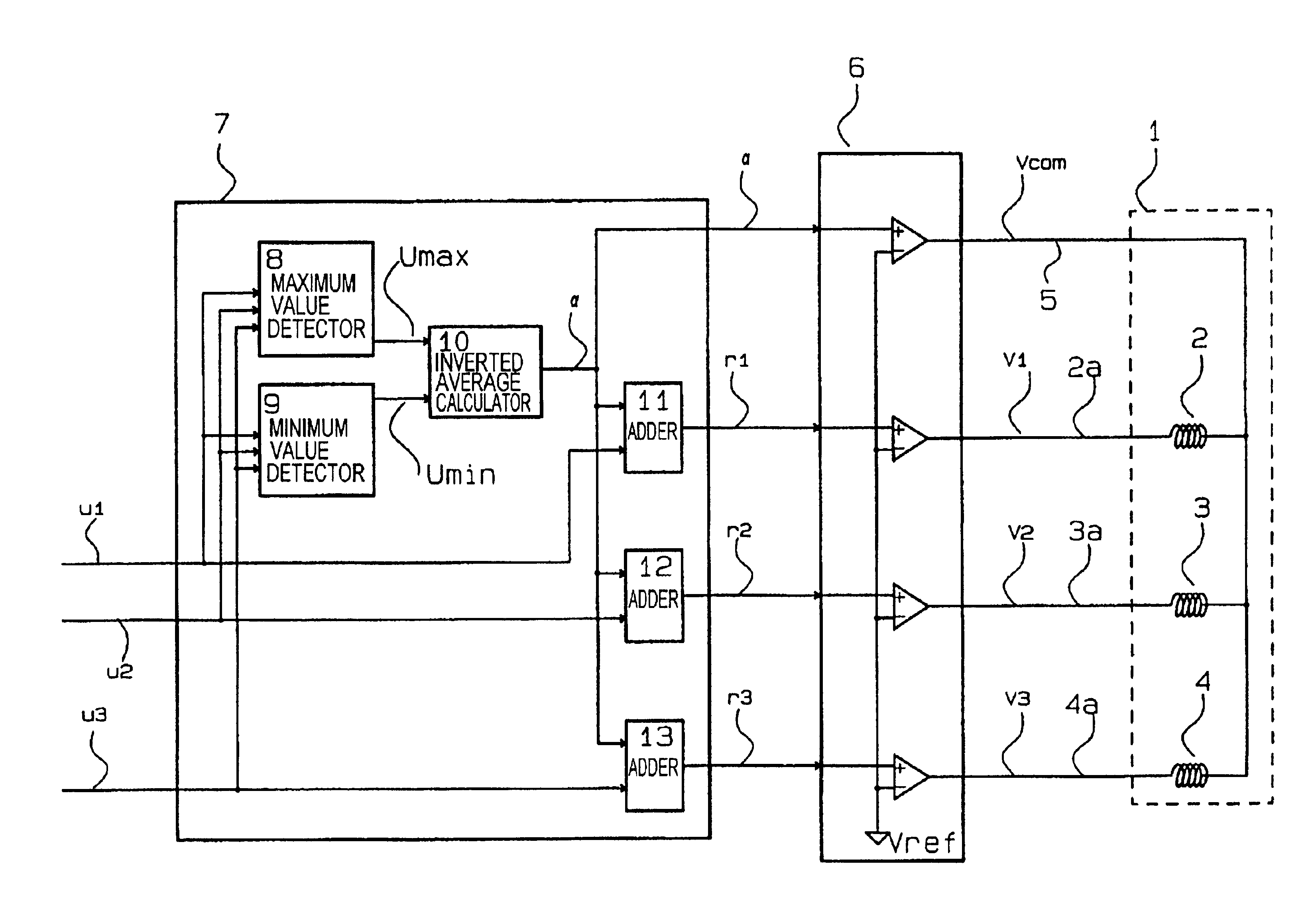
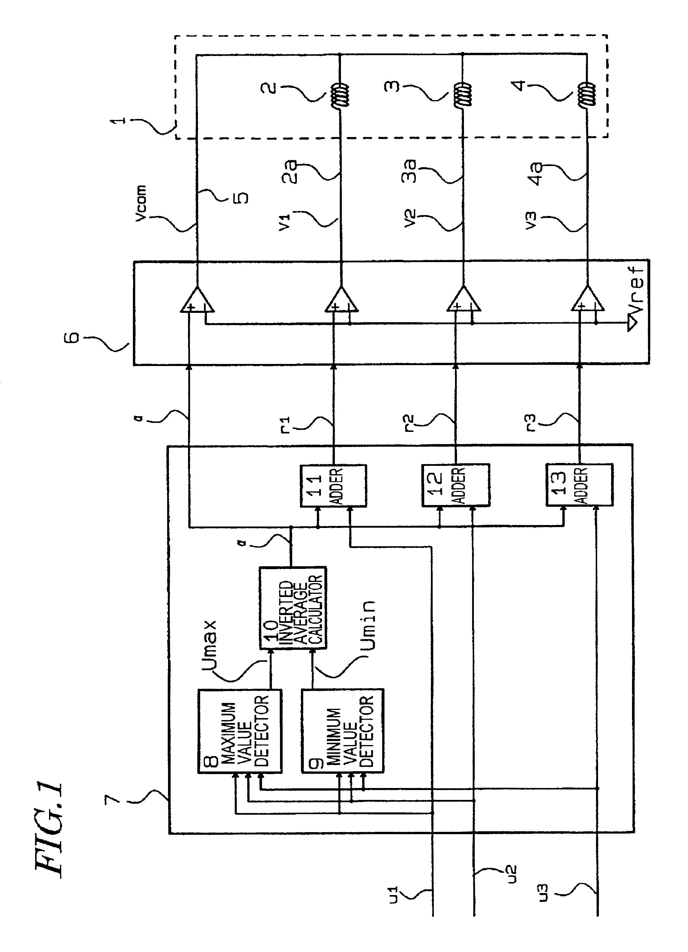
[0068]A circuit element driver according a first specific preferred embodiment of the present invention will be described with reference to FIGS. 1 and 2. FIG. 1 is a block diagram illustrating the circuit element driver of the first preferred embodiment.

[0069]The circuit element driver of this preferred embodiment drives a spindle motor 1. The spindle motor 1 includes three coils 2, 3 and 4 as respective two-terminal circuit elements. These coils 2, 3 and 4 are connected together to a common terminal 5 at one terminal thereof and to individual terminals 2a, 3a and 4a at the other terminal thereof, respectively. The common terminal 5 and individual terminals 2a, 3a and 4a have been extended from the spindle motor 1. That is to say, four terminals have been extended for three coils.

[0070]The circuit element driver of this preferred embodiment includes a driving section 6 and a control section 7. The driver receives voltage instruction values u1, u2 and U3 as instruction values of a f...

embodiment 2

[0089]Hereinafter, a circuit element driver according to a second specific preferred embodiment of the present invention will be described. The second preferred embodiment to be described below relates to a disk drive including a lens driver and a circuit element driver for use to control the lens driver. FIG. 3 illustrates a lens driving section 20 of a lens driver. As shown in FIG. 3, the lens driving section 20 includes lens 19, tracking coils 21, focus coils 22 and tilt coil 23. The lens 19 is held by a lens holder 16 and the tracking, focus and tilt coils 21, 22 and 23 are fixed to the lens holder 16. The tracking coils 21 actually include four coils that are connected in series together and the focus coils 22 actually include two coils that are also connected in series together.

[0090]These three types of coils 21, 22 and 23 are connected in common to a conductive elastic member 17a at one terminal thereof. The tracking coils 21, focus coils 22 and tilt coil 23 are respectively...

embodiment 3

[0120]A circuit element driver according to a third specific preferred embodiment of the present invention is also used to drive a lens driver for an optical disk drive as in the second preferred embodiment described above. The circuit element driver of this preferred embodiment performs a pulse width modulation (PWM) control.

[0121]FIG. 8 is a block diagram illustrating a circuit element driver according to the third preferred embodiment. As in the second preferred embodiment described above, the lens driver 20 includes the tracking coil 21, focus coil 22 and tilt coil 23. As already described in detail for the second preferred embodiment, these three coils 21, 22 and 23 are connected in common to a single conductive elastic member at one terminal thereof and also connected to their respective conductive elastic members at the other terminal thereof. The former conductive elastic member, connected in common to the three coils 21, 22 and 23, and the latter three conductive elastic me...


PUM

PropertyMeasurementUnit
voltageaaaaaaaaaa
voltageaaaaaaaaaa
voltageaaaaaaaaaa

Abstract

A circuit element driver includes a control section and a driving section. The control section receives a number n of instruction values of a first group (where n≧2) and produces and outputs a number p of instruction values of a second group (where (n+1)≦p<2n) in accordance with the n instruction values of the first group. The instruction values of the first group are issued to generate voltages to be applied to n two-terminal circuit elements. The driving section generates and outputs p drive voltages in accordance with the p instruction values of the second group. At least one of the p drive voltages changes with at least one of the instruction values of the first group and is applied in common to two or more of the circuit elements at one terminal thereof.

Description

BACKGROUND OF THE INVENTION[0001]1. Field of the Invention[0002]The present invention relates to an apparatus and method for driving circuit elements.[0003]2. Description of the Related Art[0004]To apply voltages to two-terminal circuit elements such as coils or resistors, two interconnections are needed for each of the circuit elements. For example, six interconnections are necessary to apply respective voltages to three coils independently.[0005]A lens driver for use in an optical disk drive is one of such apparatuses for applying respective voltages to a plurality of two-terminal circuit elements independently. For example, according to the technique disclosed in Japanese Laid-Open Publication No. 7-65397, the tilt of the optical axis of an optical head with respect to a disk may be corrected by the tilt of an objective lens to be driven by a lens driver.[0006]An apparatus like this drives the objective lens at three degrees of freedom and needs three types of coils. Specifically...

Claims


Application Information

Patent Timeline
Patent Type & Authority Patents(United States)
IPC IPC(8): G11B7/09G11B7/095
CPCG11B7/093G11B7/0932G11B7/0956
Inventor IKAWA, YOSHIHIROMUSHIKA, YOSHIHIROTAKIZAWA, TERUYUKI
Owner PANASONIC CORP
Why Eureka
Try Eureka