Reel for a harvesting assembly

a technology for reels and harvesting parts, applied in the field of reels for harvesting parts, can solve the problems of obstructing the operator's view, disadvantage of center tubes, and weight of reels, and achieve the effect of sufficient stability

Active Publication Date: 2005-12-27
DEERE & CO
View PDF10 Cites 7 Cited by
  • Summary
  • Abstract
  • Description
  • Claims
  • Application Information

AI Technical Summary

Benefits of technology

[0004]Thus, the present invention is directed to providing a sturdy and stable structure for a lightweight and open center reel for a harvesting platform.
[0005]The invention includes a reel having a framework that includes longitudinal bat tubes and struts around the reel perimeter that connect adjacent bat tubes. This framework provides sufficient stability so that additional supporting elements such as a center tube that normally extends across the length of the reel can be eliminated from the interior space between the bat tubes. The structure of the present invention results in a reel that is relatively lightweight and provides the operator an unobstructed view of the harvesting assembly.

Problems solved by technology

However, the center tube is a disadvantage because the tube increases the weight of the reel and obstructs the operator's view of the sickle mechanism, particularly the cutter bar and regions situated in front of the cutter bar.
However, the unstable structure of the unsupported reel would not be suitable for larger operating widths such as on harvesting platforms because of stability risks.

Method used


Image

  • Reel for a harvesting assembly
  • Reel for a harvesting assembly
  • Reel for a harvesting assembly

Examples


Embodiment Construction

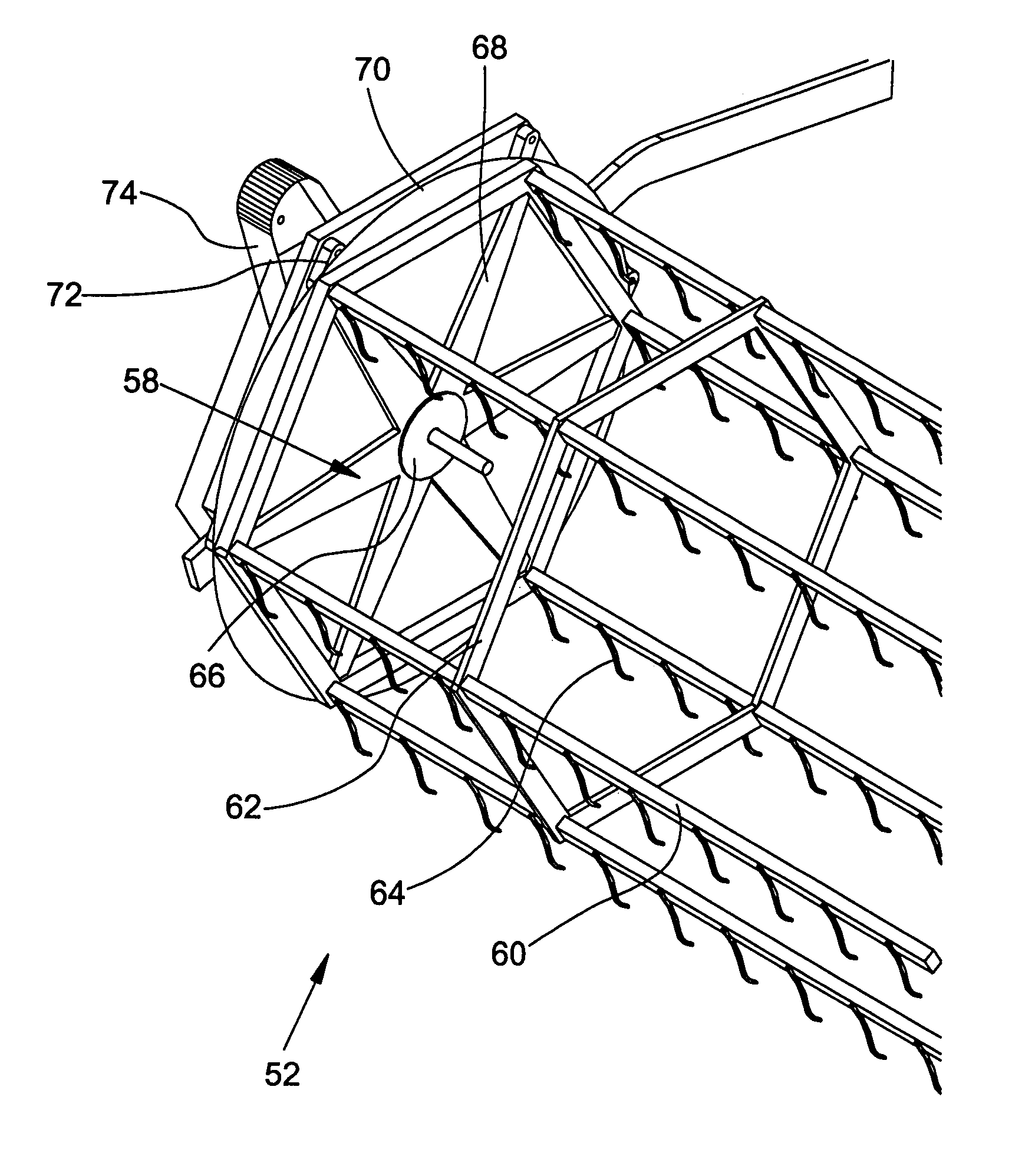
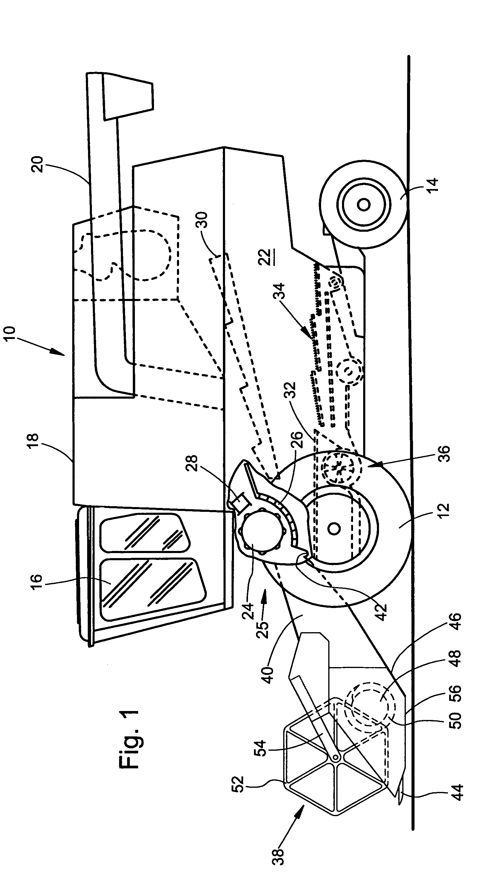
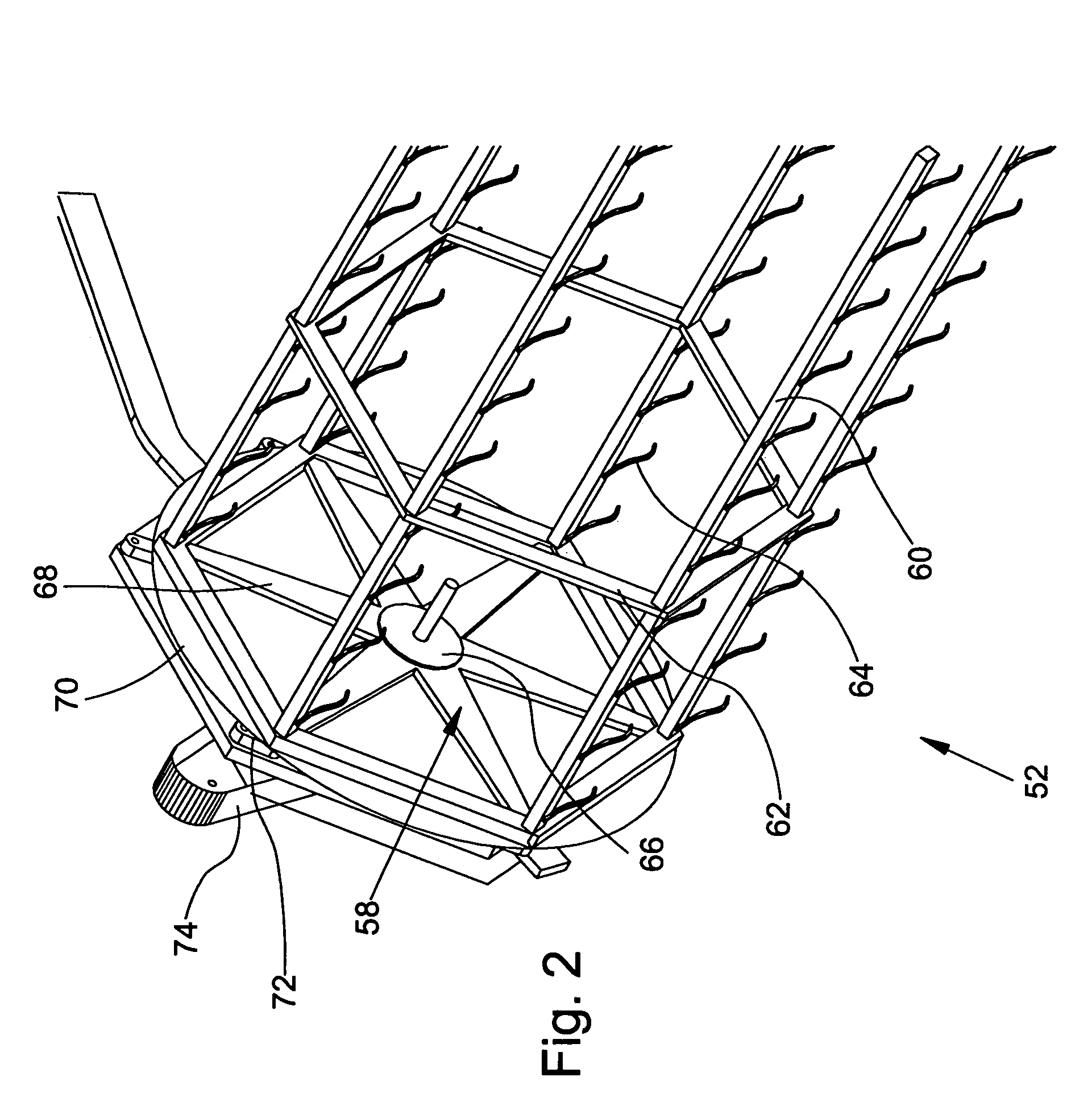
[0009]A combine-harvester 10 shown in FIG. 1 is carried on driven front wheels and steerable rear wheels 12 and 14, respectively. An operator cab 16 is provided from which an operator is able to operate the combine-harvester. A grain tank 18 is situated behind the operator cab 16 and a delivery tube 20 can deliver the grain outward. The grain tank 18 is supported on a frame 22. The harvested crop is separated into its larger and smaller fractions by means of a threshing drum 24, a threshing basket 26 and a turning drum 28, for example. The harvested crop is additionally separated on ensuing straw rockers 30, as well as a preparatory base 32 and screens 34, so that the threshed-out fraction of the crop is ultimately conveyed into the grain tank 18 while the larger constituents of the harvested crop are deposited on the ground by the straw rockers 30. Lightweight residuals such as chaff are blown off the screens 34 and onto the ground by a blower 36. The standing crop that is picked u...


PUM


Abstract

A harvesting assembly includes a platform reel. The reel includes bat tubes extending longitudinally across the length of the reel. The bat tubes are mounted at their outer ends to opposed spider support elements each having a center rotatable hub. The bat tubes carry tines for feeding harvested crop to the harvesting platform. The interior of the reel is free of supporting elements such as a center tube extending across the length of the reel. Perimeter struts connect adjacent bat tubes and provide a supporting framework together with the bat tubes for the reel.

Description

BACKGROUND OF THE INVENTION[0001]This invention pertains to a platform reel for a harvesting assembly with bat tubes that extend across the width of the reel. The bat tubes are supported by spider supports at their outer ends and by perimeter struts at various longitudinal positions along the bat tubes. The interior space between the bat tubes does not contain a longitudinal supporting element such as a center tube that normally extends over the length of the reel.[0002]Harvesting platform reels are utilized on harvesting assemblies, particularly on sickle mechanisms, in order to feed standing crop to a cutter bar and harvested crop to a transverse conveyor device. U.S. Pat. No. 3,145,520 describes a reel with bat tubes and tines mounted thereon, which are supported on spider-type carrying elements distributed over the width of the reel. The bat tubes are rotatably supported on the spider-type carrying elements and are rotated by means of an off-center driving mechanism to orient th...

Claims


Application Information

Patent Timeline
Patent Type & Authority Patents(United States)
IPC IPC(8): A01D57/02
CPCA01D57/02
Inventor LANZINGER, BERNHARD
Owner DEERE & CO
Why Eureka
Try Eureka