Tire forming system and tire forming method

a technology tire forming method, which is applied in the field of tire forming system, can solve the problems of inability to respond to one to one, stagnation of unvulcanized tires, and increase in time, so as to facilitate a different stage of tire forming and increase the production efficiency of tires

Inactive Publication Date: 2005-12-27
THE YOKOHAMA RUBBER CO LTD
View PDF15 Cites 21 Cited by
  • Summary
  • Abstract
  • Description
  • Claims
  • Application Information

AI Technical Summary

Benefits of technology

[0006]An object of the invention is to provide a tire forming system and a tire forming method, which facilitate a stage switchover of tires different in specification and make it possible to greatly increase a production efficiency of the tire.
[0016]And, if it becomes possible to form the tires different in specification in one unit, since it becomes null that unvulcanized tires waiting for being vulcanized in a specified metal mold are accumulated, it is possible to improve an operating efficiency of the metal mold, thereby reducing the goods in process of the unvulcanized tires. Further, in the above tire forming system, since parts preparation process is connected to each forming machine, it is possible to reduce the goods in process of intermediate members. As a result, it becomes possible to reduce costs of the goods in process, a management and auxiliary members, so that it becomes possible to greatly increase the production efficiency of the tire and, additionally, manufacture the tire stable in its quality.
[0019]Further, as the injection unit it is preferable to use a plunger type injection unit in which there is accommodated, for the respective rubber parts, a rubber amount corresponding at least to the specification of the formed tire. Such a plunger type injection unit can precisely inject a required volume of unvulcanized rubber for the respective rubber parts and, moreover, can easily change the require volume for every tire.

Problems solved by technology

However, a vulcanizing cycle time consumed for vulcanizing one tire is about 5 to 10 times a forming cycle time consumed for forming one tire, so that a correspondence of one to one has been impossible.
Therefore, even if tires of specified size are continuously formed in a lot unit, it is impossible to use metal molds for vulcanizing the tires of specified size in agreement with the forming cycle time and, as a result, the unvulcanized tires stagnate as intermediate goods in process, i.e., a lead time increases, so that the production efficiency has been reduced.
Therefore, material expenses and management costs of the intermediate members increase, so that a production cost of the tire has been raised.

Method used


Image

  • Tire forming system and tire forming method
  • Tire forming system and tire forming method
  • Tire forming system and tire forming method

Examples


Embodiment Construction

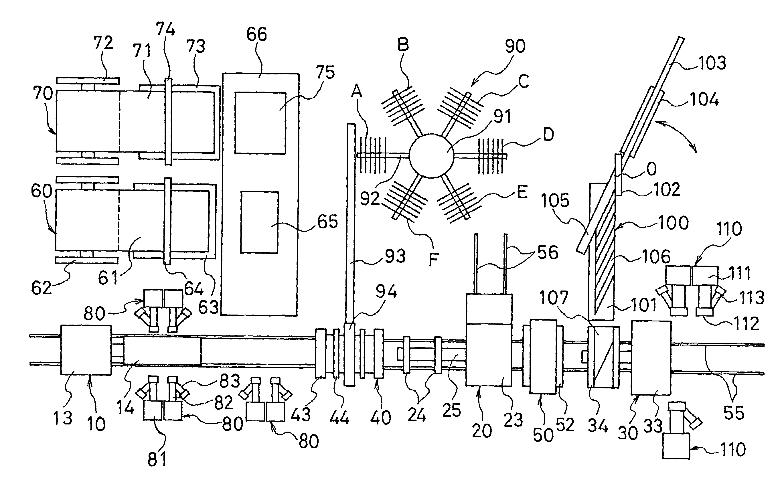
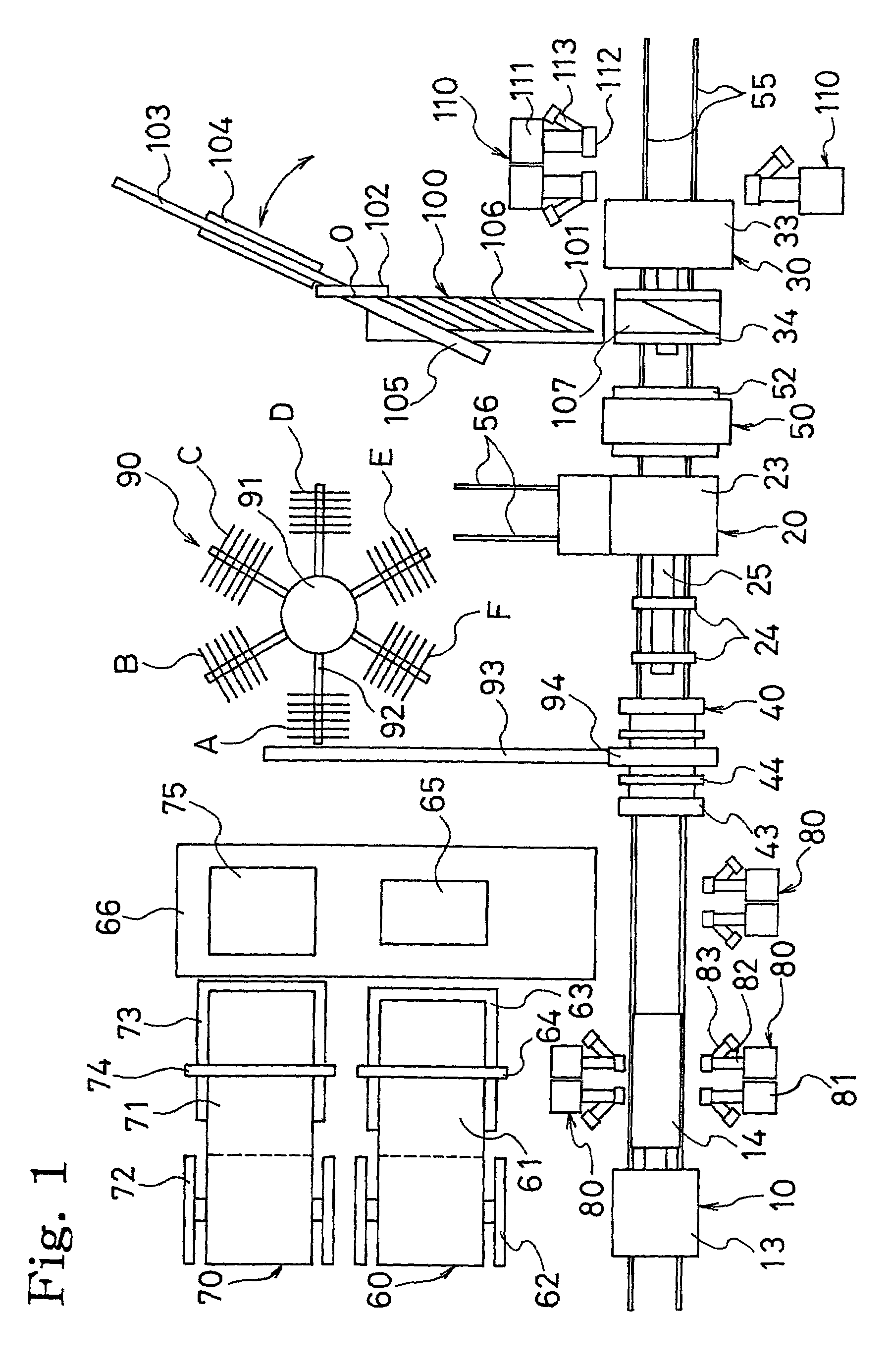
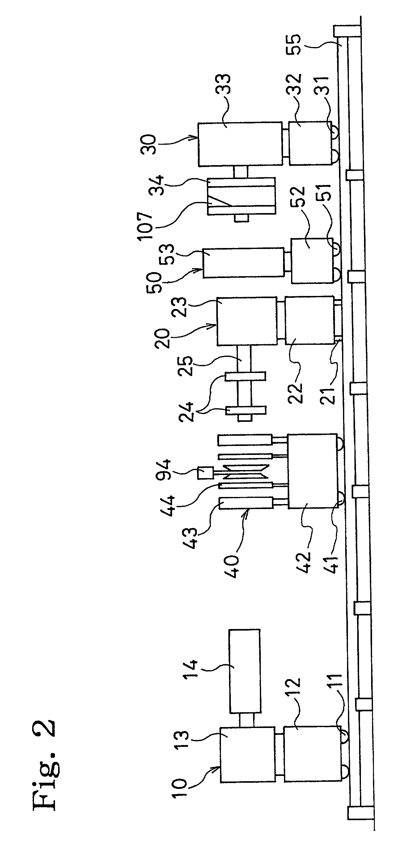
[0037]FIG. 1 is a plan view showing a tire forming system according to an embodiment of the invention, and FIG. 2 a side view of the same. However, in FIG. 2, a part of constitution is omitted.

[0038]This system is a tire forming system including a band forming machine 10, a shaping forming machine 20 and a belt / tread forming machine 30, and having a band transfer 40 and a belt transfer 50 as transport means for delivering a semi-fabricated product to the respective forming machines 10, 20, 30. Each of the band forming machine 10, the shaping forming machine 20 and the belt / tread forming machine 30 is constituted such that setting conditions of a tire size can be optionally changed. Further, the band forming machine 10, the band transfer 40, the belt transfer 50 and the belt / tread forming machine 30 are arranged so as to be movable on one pair of left / right linearly laid rails 55. The shaping forming machine 20 is arranged so as to be movable on one pair of left / right rails 56 inters...


PUM

PropertyMeasurementUnit
widthaaaaaaaaaa
widthaaaaaaaaaa
thicknessaaaaaaaaaa

Abstract

A tire forming system includes a band forming machine, a shaping forming machine, a belt / tread forming machine, means for supplying a band member and means for supplying a belt / tread member. The means for supplying the band member include an inner liner supply means, carcass supply means, band rubber parts supply means and bead supply means. The means for supplying the belt / tread member include belt supply means and tread rubber parts supply means. The means for supplying the band member and the means for supplying the belt / tread member are operative to cooperate with one another to continuously in series form a plurality of tires having different tire sizes.

Description

BACKGROUND OF THE INVENTION[0001]The present invention relates to a tire forming system for consistently forming a pneumatic tire from materials and a tire forming method using the system and, more detailedly, relates to a tire forming system and a tire forming method, which facilitate a stage switchover of tires different in specification and make it possible to greatly increase a production efficiency of the tire.[0002]In the pneumatic tire, there are many sizes owing to differences in oblate ratio and tread width even if bead inner diameters are the same. Further, even if the tire sizes are the same, there is the fact that kinds of compounds and the like are finely assorted in compliance with use objects.[0003]In case of forming such many and various pneumatic tires, setting conditions of a forming machine for the tire size can be almost automatically changed at present, but a lot of time is required in a stage switchover of members supplied to the forming machine. Therefore, hit...

Claims


Application Information

Patent Timeline
Patent Type & Authority Patents(United States)
IPC IPC(8): B29D30/08B29D30/00B29D30/62
CPCB29D30/00B29D30/0016B29D30/005B29D30/60B29D2030/0055B29D2030/202B29D2030/206B29D2030/207B29D30/20B29D2030/204B29D30/08
Inventor OKADA, NOBORUHASEGAWA, HARUHISATAKAOKA, TATSUYATAKASU, ICHIROFUKUZAWA, HISAYOSHIIMAMIYA, SUSUMUIIDA, EIICHITAKE, TOSHIHIKO
Owner THE YOKOHAMA RUBBER CO LTD
Why Eureka
Try Eureka