Battery including carbon foam current collectors

a carbon foam and current collector technology, applied in the direction of cell components, electrochemical generators, nickel accumulators, etc., can solve the problems of lead-acid batteries, corrosion of lead current collectors of positive plates, and constant corrosion of current collectors of each positive pla

Inactive Publication Date: 2005-12-27
FIREFLY ENERGY INC
View PDF169 Cites 100 Cited by
  • Summary
  • Abstract
  • Description
  • Claims
  • Application Information

AI Technical Summary

Problems solved by technology

A notable limitation on the durability of lead-acid batteries is corrosion of the lead current collector of the positive plate.
Once the electrolyte (e.g., sulfuric acid) is added to the battery and the battery is charged, the current collector of each positive plate is continually subjected to corrosion due to its exposure to sulfuric acid and to the anodic potentials of the positive plate.
One of the most damaging effects of this corrosion of the positive plate current collector is volume expansion.
As a result, battery capacity may drop, and eventually, the battery will reach the end of its service life.
Additionally, at advanced stages of corrosion, internal shorting within the current collector and rupture of the cell case may occur.
Both of these corrosion effects may lead to failure of one or more of the cells within the battery.
Substituting graphite plates for the lead current collectors may, therefore, lengthen the life of a lead-acid battery.
While the battery of the '390 patent may potentially offer a lengthened service life as a result of reduced corrosion at the positive plate, the graphite plates of the '390 patent are problematic.
The relatively small surface area of the graphite plates of the '390 patent results in poorly performing batteries that have slow charging speeds.
Additionally, the graphite plates of the '390 patent lack the toughness of lead current collectors.
The dense, graphite plates of the '390 patent are brittle and may fracture when subjected to physical shock or vibration.
Any fracturing of the graphite plates would lead to the same problems caused by volume expansion of ordinary lead current collectors.
Therefore, despite offering an increased resistance to corrosion compared to conventional lead current collectors, the brittle nature of the graphite plates of the '390 patent could actually result in battery service lives shorter than those possible through use of ordinary lead current collectors.

Method used


Image

  • Battery including carbon foam current collectors
  • Battery including carbon foam current collectors
  • Battery including carbon foam current collectors

Examples


Embodiment Construction

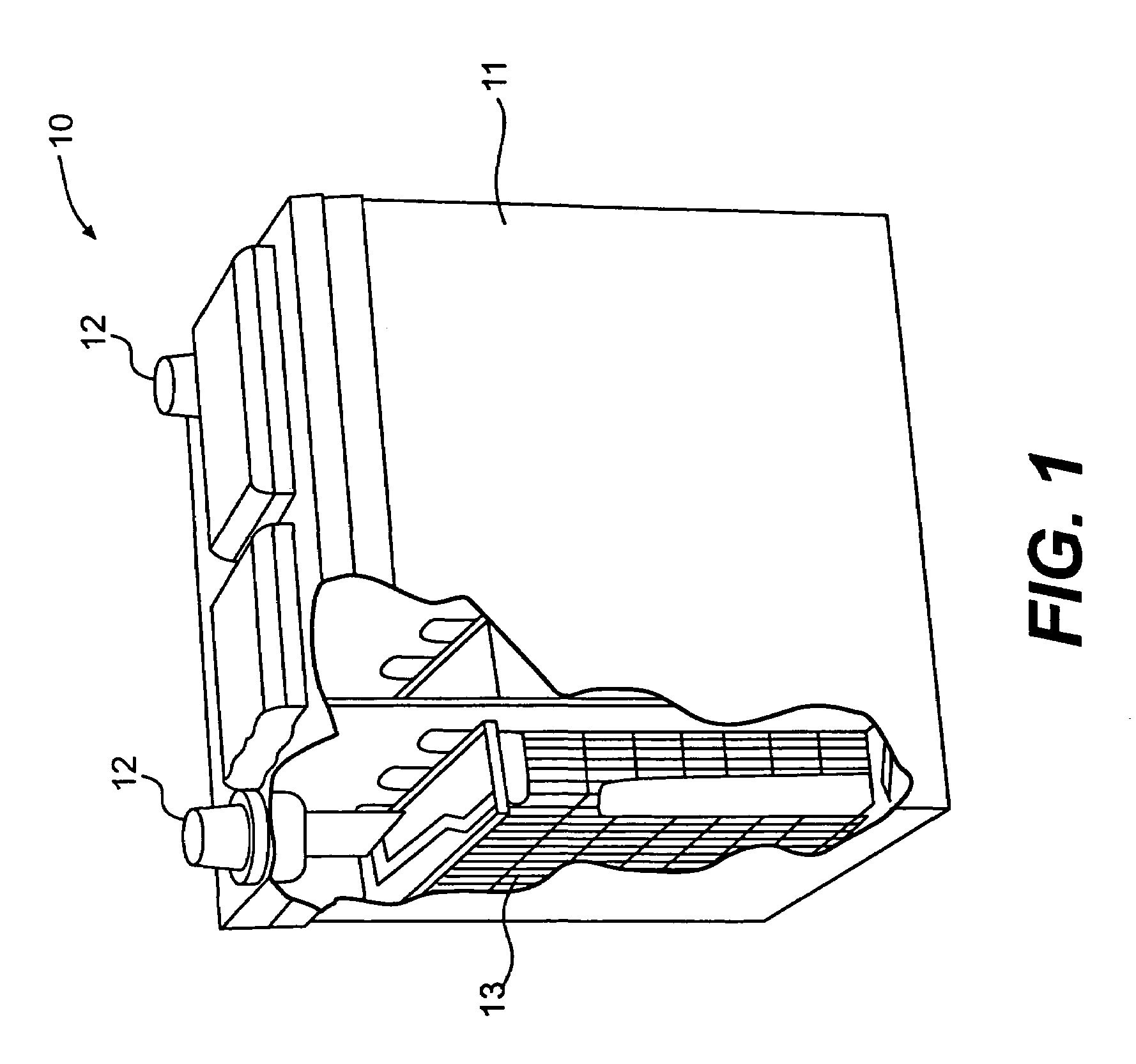
[0018]FIG. 1 illustrates a battery 10 in accordance with an exemplary embodiment of the present invention. Battery 10 includes a housing 11 and terminals 12, which are external to housing 11. At least one cell 13 is disposed within housing 11. While only one cell 13 is necessary, multiple cells may be connected in series or in parallel to provide a desired total potential of battery 10.

[0019]Each cell 13 may be composed of alternating positive and negative plates immersed in an electrolytic solution. The electrolytic solution composition may be chosen to correspond with a particular battery chemistry. For example, while lead acid batteries may include an electrolytic solution of sulfuric acid and distilled water, nickel-based batteries may include alkaline electrolyte solutions that include a base, such as potassium hydroxide, mixed with water. It should be noted that other acids and other bases may be used to form the electrolytic solutions of the disclosed batteries.

[0020]The posi...


PUM

PropertyMeasurementUnit
open porosityaaaaaaaaaa
densityaaaaaaaaaa

Abstract

A battery having a current collector constructed of carbon foam. The carbon foam includes a network of pores into which a chemically active material is disposed to create either a positive or negative plate for the battery. The carbon foam resists corrosion and exhibits a large amount of surface area. The invention includes a method for making the disclosed carbon foam current collector used in the battery.

Description

[0001]This application is a continuation-in-part of U.S. application Ser. No. 10 / 183,471 filed on Jun. 28, 2002, which is incorporated herein by reference.TECHNICAL FIELD[0002]This invention relates generally to current collectors for a battery and, more particularly, to carbon foam current collectors for a battery.BACKGROUND[0003]Electrochemical batteries, including, for example, lead acid and nickel-based batteries, among others, are known to include at least one positive current collector, at least one negative current collector, and an electrolytic solution. In lead acid batteries, for example, both the positive and negative current collectors are constructed from lead. The role of these lead current collectors is to transfer electric current to and from the battery terminals during the discharge and charging processes. Storage and release of electrical energy in lead acid batteries is enabled by chemical reactions that occur in a paste disposed on the current collectors. The po...

Claims


Application Information

Patent Timeline
Patent Type & Authority Patents(United States)
IPC IPC(8): B05D5/12H01M4/66C01B31/00C01B31/02H01MH01M4/02H01M4/04H01M4/14H01M4/20H01M4/48H01M4/52H01M4/56H01M4/58H01M4/64H01M4/80H01M8/00H01M10/06H01M10/18H01M10/20H01M10/30H01M50/541
CPCH01M4/14H01M4/20H01M4/663H01M4/808Y02T10/7016H01M10/06H01M10/30Y02E60/126Y02E60/10
Inventor KELLEY, KURTIS CHADVOTOUPAL, JOHN J.
Owner FIREFLY ENERGY INC
Why Eureka
Try Eureka