Planar inverted F antennas including current nulls between feed and ground couplings and related communications devices

a technology current nulls, applied in the field of inverted f antennas, can solve the problems of increasing production costs, bandwidth degradation at the low-band element,

Active Publication Date: 2005-12-27
SONY CORP
View PDF24 Cites 150 Cited by
  • Summary
  • Abstract
  • Description
  • Claims
  • Application Information

AI Technical Summary

Problems solved by technology

Unfortunately, the increase in the coupling between the two elements by this configuration may result in degradation in bandwidth at the low-band element.
In addition, the parasitic element may dictate tight manufacturing tolerances for proper operation that may increase production costs.

Method used


Image

  • Planar inverted F antennas including current nulls between feed and ground couplings and related communications devices
  • Planar inverted F antennas including current nulls between feed and ground couplings and related communications devices
  • Planar inverted F antennas including current nulls between feed and ground couplings and related communications devices

Examples


Embodiment Construction

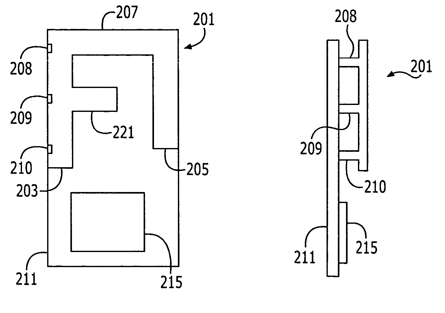
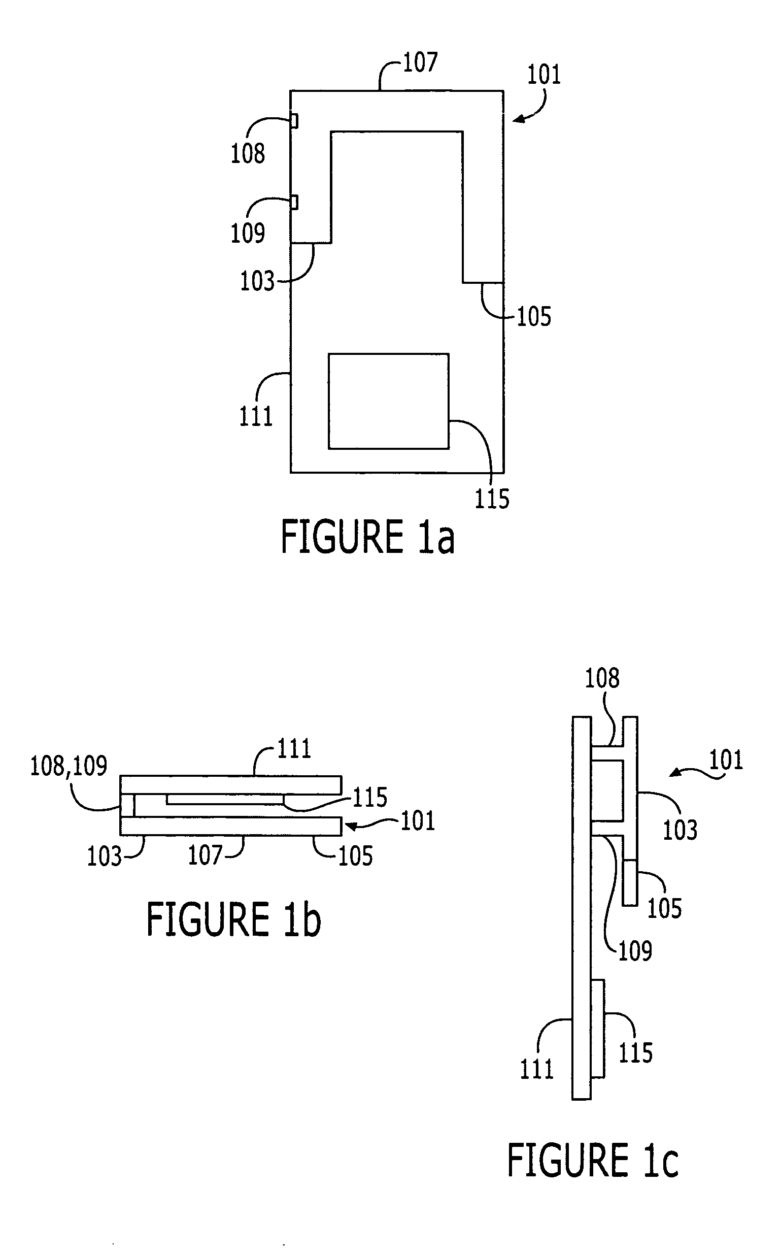
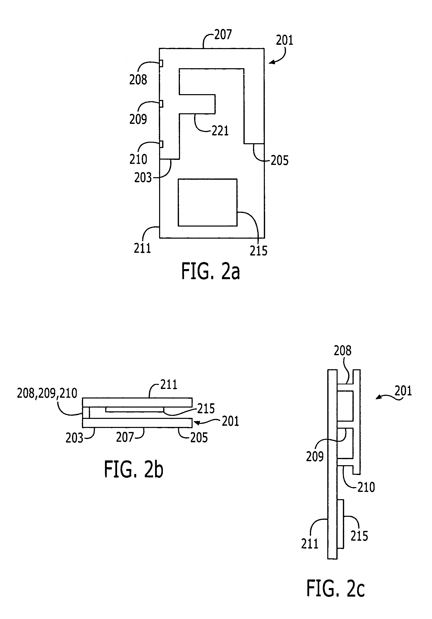
[0038]The present invention will now be described more fully hereinafter with reference to the accompanying drawings, in which embodiments of the invention are shown. The invention may, however, be embodied in different forms and should not be construed as limited to the embodiments set forth herein. Rather, these embodiments are provided so that this disclosure will be thorough and complete, and will fully convey the scope of the invention to those skilled in the art. In the drawings, the dimensions of various elements may be exaggerated for clarity. It will also be understood that when an element is referred to as being “coupled” or “connected” to another element, it can be directly coupled or connected to the other element, or intervening elements may also be present. Similarly, when an element is referred to as being “on” another element, it can be directly on the other element, or intervening elements may also be present. Like numbers refer to like elements throughout. This dis...


PUM


Abstract

A planar inverted F antenna may be configured for operation at an operating frequency band, and the planar inverted F antenna may include first, second, and third antenna segments, a reference voltage coupling, and a feed coupling. The first and second antenna segments may be separated by at least approximately 3 mm, and the third antenna segment may couple the first and second antenna segments. The reference voltage and feed couplings may both be provided on the first antenna segment, and a current null may be present between the feed and reference voltage couplings at the operating frequency band. Related communications devices are also discussed.

Description

FIELD OF THE INVENTION[0001]The present invention relates to the field of antennas, and more particularly to planar inverted F antennas and related communications devices.BACKGROUND[0002]The size of wireless terminals has been decreasing with many contemporary wireless terminals being less than 11 centimeters in length. Correspondingly, there is increasing interest in small antennas that can be utilized as internally mounted antennas for wireless terminals. Inverted-F antennas, for example, may be well suited for use within the confines of wireless terminals, particularly wireless terminals undergoing miniaturization. Inverted-F antennas may provide small size, low cost, and mechanical robustness. Typically, conventional inverted-F antennas may include a conductive element that is maintained in a spaced apart relationship with a ground plane. Exemplary inverted-F antennas are described, for example, in U.S. Pat. Nos. 5,684,492 and 5,434,579, which are incorporated herein by referenc...

Claims


Application Information

Patent Timeline
Patent Type & Authority Patents(United States)
IPC IPC(8): H01Q1/24H01Q5/00H01Q5/10H01Q5/371H01Q9/04
CPCH01Q1/243H01Q5/371H01Q9/0442H01Q9/0421
Inventor VANCE, SCOTT LADELLHAYES, GERARD
Owner SONY CORP
Why Eureka
Try Eureka