System for precise rotational and positional tracking

a technology of rotational and positional tracking and positioning information, applied in the field of position tracking, to achieve the effect of high accuracy in the tracking information collected

Inactive Publication Date: 2005-12-27
INFORMATION DECISION TECH
View PDF5 Cites 111 Cited by
  • Summary
  • Abstract
  • Description
  • Claims
  • Application Information

AI Technical Summary

Benefits of technology

[0005]A purpose of the invention is to allow testing, training, and calibration of vehicle or movable structure control systems in the field via the attachment of a ...

Problems solved by technology

While the capabilities are great, the tradeoff is that the system has special requirements to operate most effectively, inc...

Method used


Image

  • System for precise rotational and positional tracking
  • System for precise rotational and positional tracking
  • System for precise rotational and positional tracking

Examples


Embodiment Construction

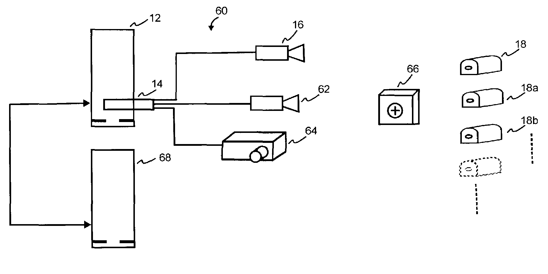
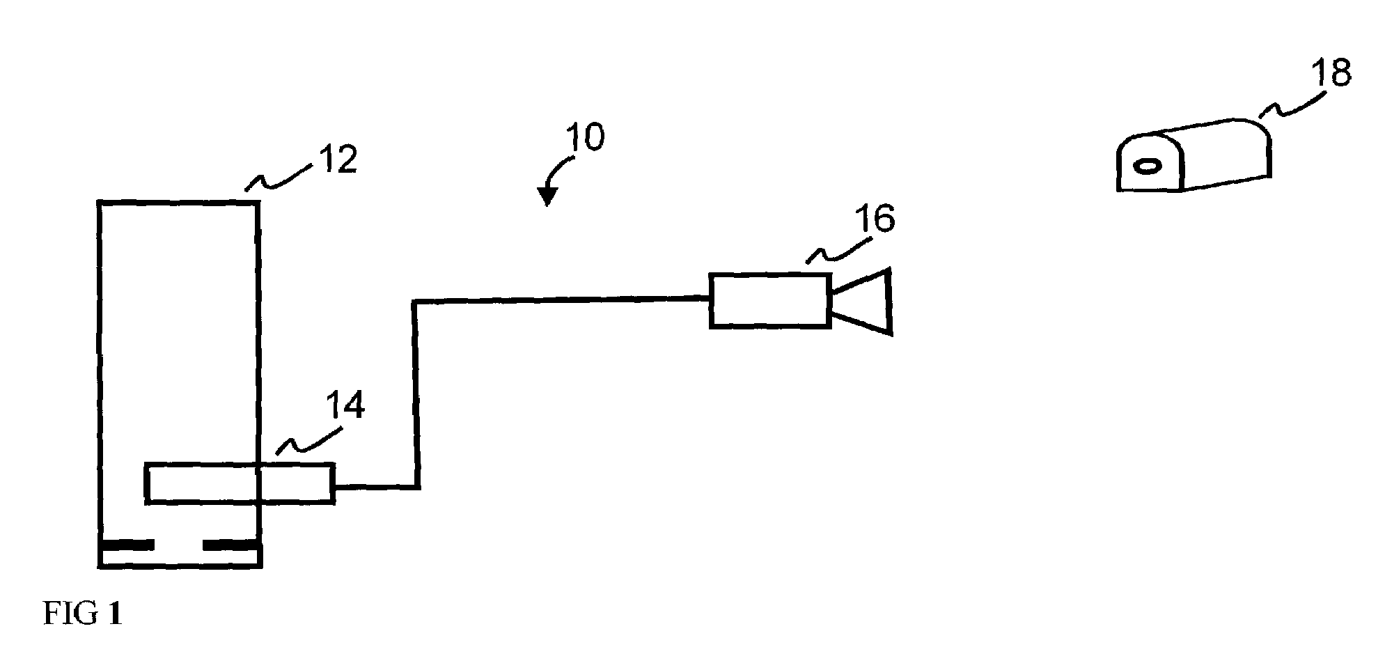
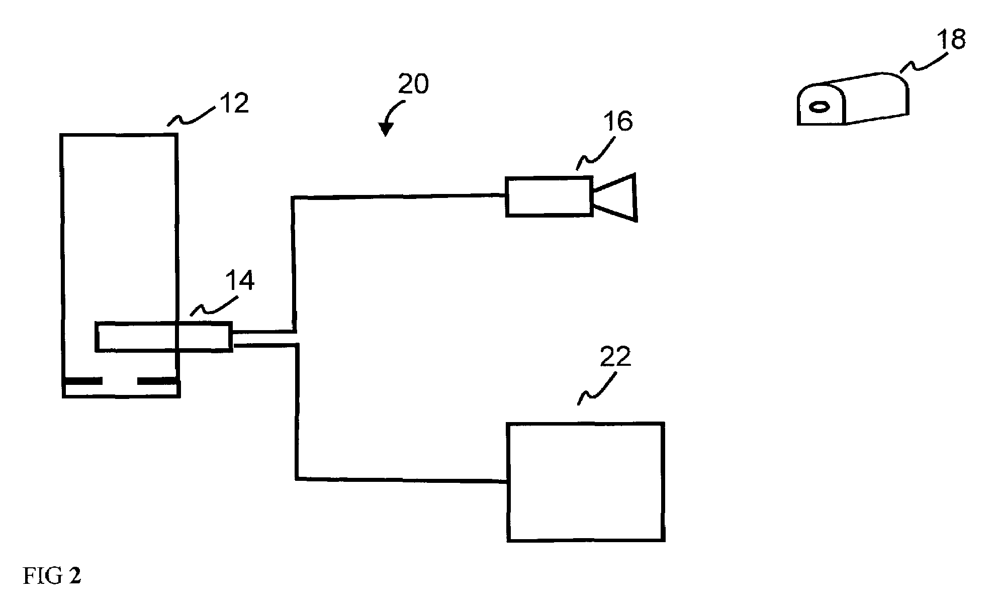
[0014]The invention consists of two major component groups: a collection of hardware for tracking and display, and a number of software components for the collection of data, interpretation of camera images, augmented reality (AR) display to the user, and control by a test administrator. The hardware system 10, FIG. 1, consists minimally of a computer 12, high-speed video camera 16, high-speed image capture board 14, and one or more actively emissive fiducials 18. If the system 20, FIG. 2 will be providing feedback to a human test subject or operator for the system being tested, then the addition of a video display device 22 is also required. The software components minimally contain code for the control of the video capture board 14, translation of the incoming image data into tracking information, and if needed, data collection for evaluation. Software for image generation is also needed if there is an output video display 22 present (for a human operator or test subject). If desi...


PUM


Abstract

A system for tracking a movable structure, comprising: at least one fiducial; and at least one video camera; wherein either the camera or the fiducial is mounted on the movable structure, so that the camera can capture an image of the fiducial as the structure moves. The image from the video camera is captured. From this, the heading of the movable structure is resolved.

Description

CROSS REFERENCE TO RELATED APPLICATION[0001]This application claims priority of Provisional patent application 60 / 329,852 filed Oct. 16, 2001.FIELD OF THE INVENTION[0002]This invention relates to the fields of position tracking, high accuracy calibration of large, movable objects, calibration, vehicle operation testing, vehicle operation training, and augmented reality (AR).COPYRIGHT INFORMATION[0003]A portion of the disclosure of this patent document contains material that is subject to copyright protection. The copyright owner has no objection to the facsimile reproduction by anyone of the patent document or the patent disclosure as it appears in the Patent and Trademark Office records but otherwise reserves all copyright works whatsoever.BACKGROUND OF THE INVENTION[0004]There are publicly known techniques whereby one or fiducials (markers that can be used to reference off of) are tracked by cameras in order to determine the pointing angle (roll, pitch, yaw) of the camera. What is...

Claims


Application Information

Patent Timeline
IPC IPC(8): H04N5/222H04N5/225
CPCH04N5/222H04N5/2224
Inventor EBERSOLE, JR., JOHN F.
Owner INFORMATION DECISION TECH
Why Eureka
Try Eureka