Carrying case for portable electronic devices
- Summary
- Abstract
- Description
- Claims
- Application Information
AI Technical Summary
Benefits of technology
Problems solved by technology
Method used
Image

Examples
Embodiment Construction
[0020]Using the drawings, the preferred embodiments of the present invention will now be explained.
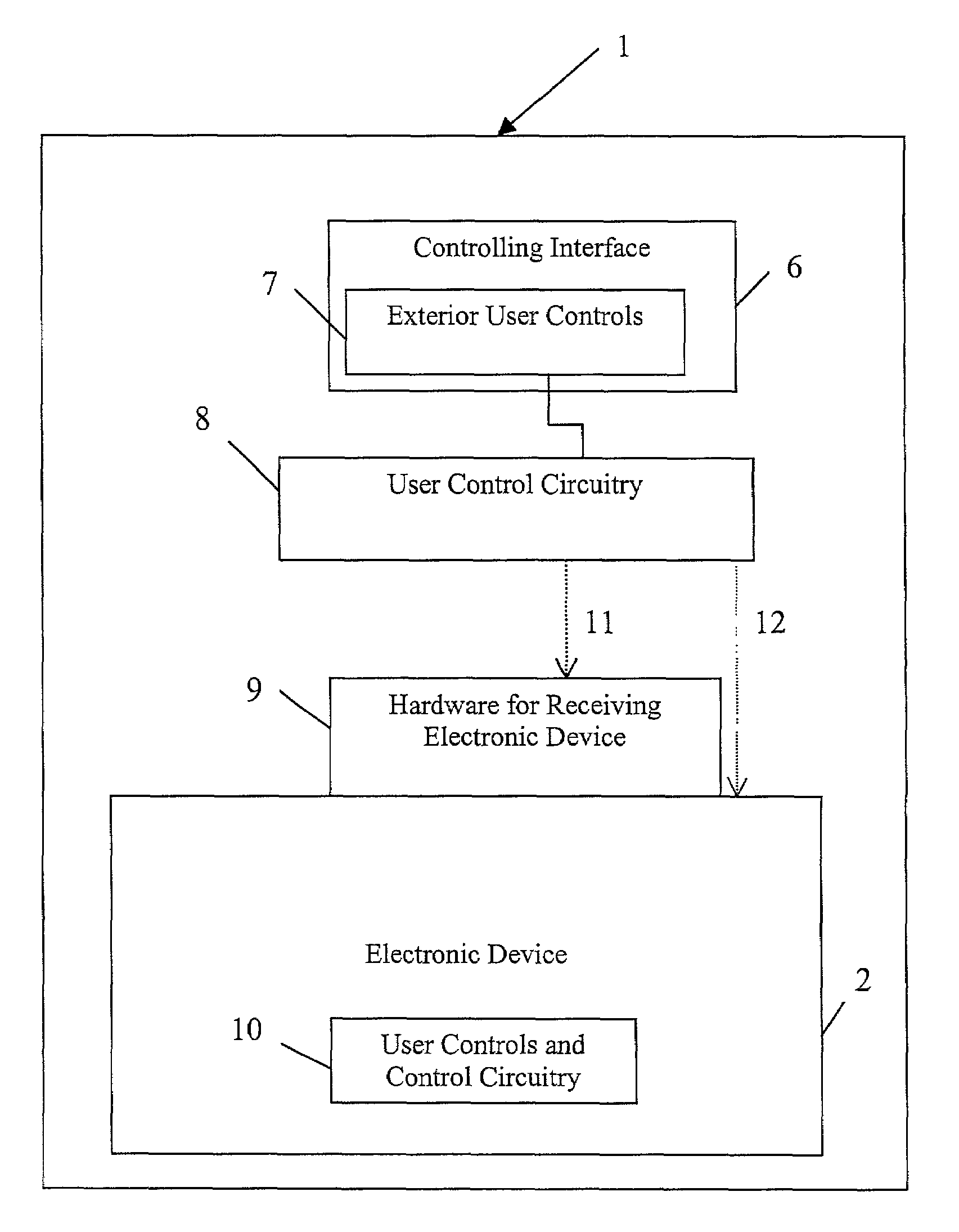
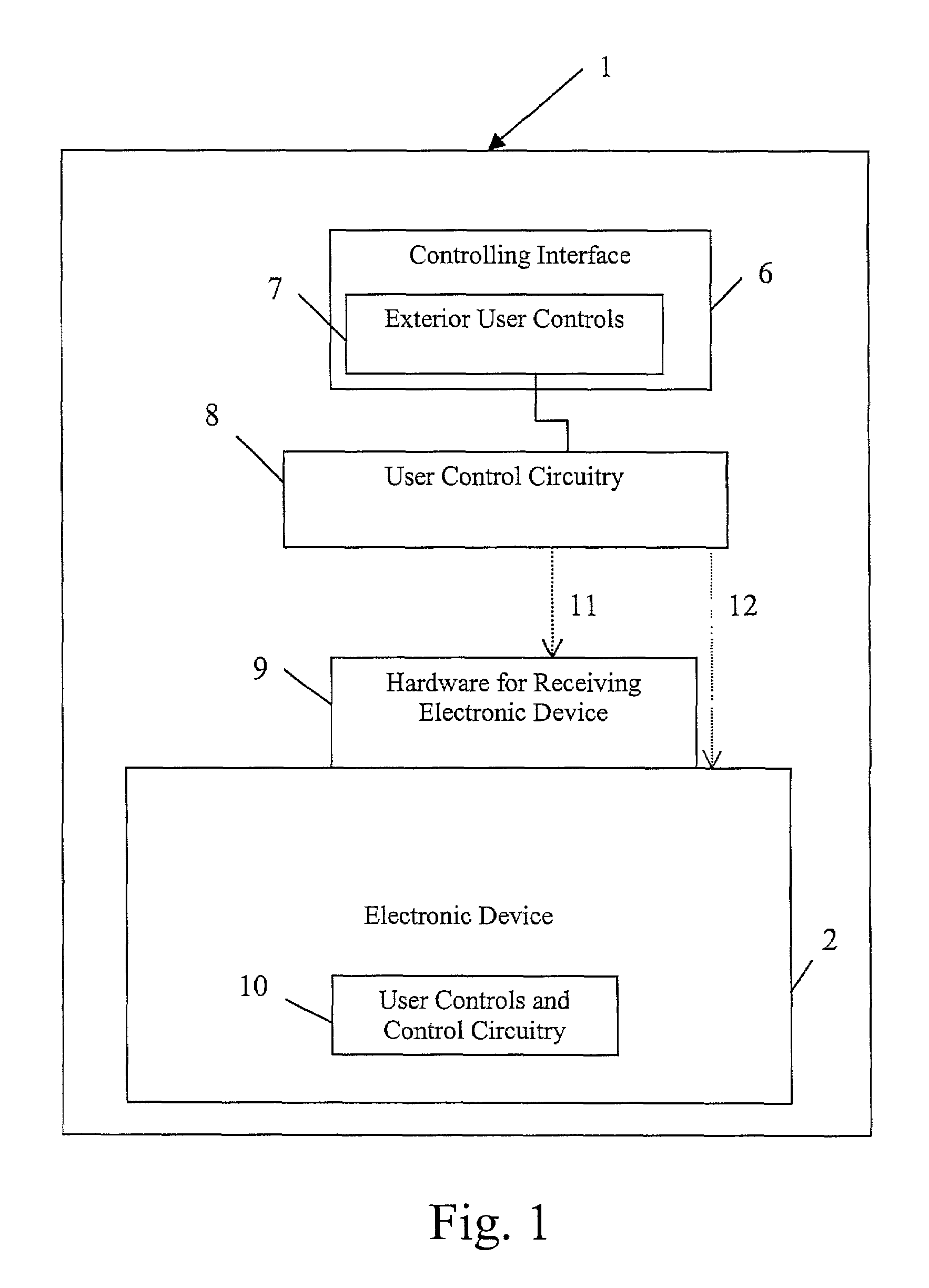
[0021]Throughout the drawings and the following discussion, the device contained within the case of the present invention is designated simply as an electronic device 2. As set forth above, the electronic device 2 can be one of many portable devices such as audio devices, video devices, pagers, telephones, cameras, electronic planners, computer processors, and other electronics.
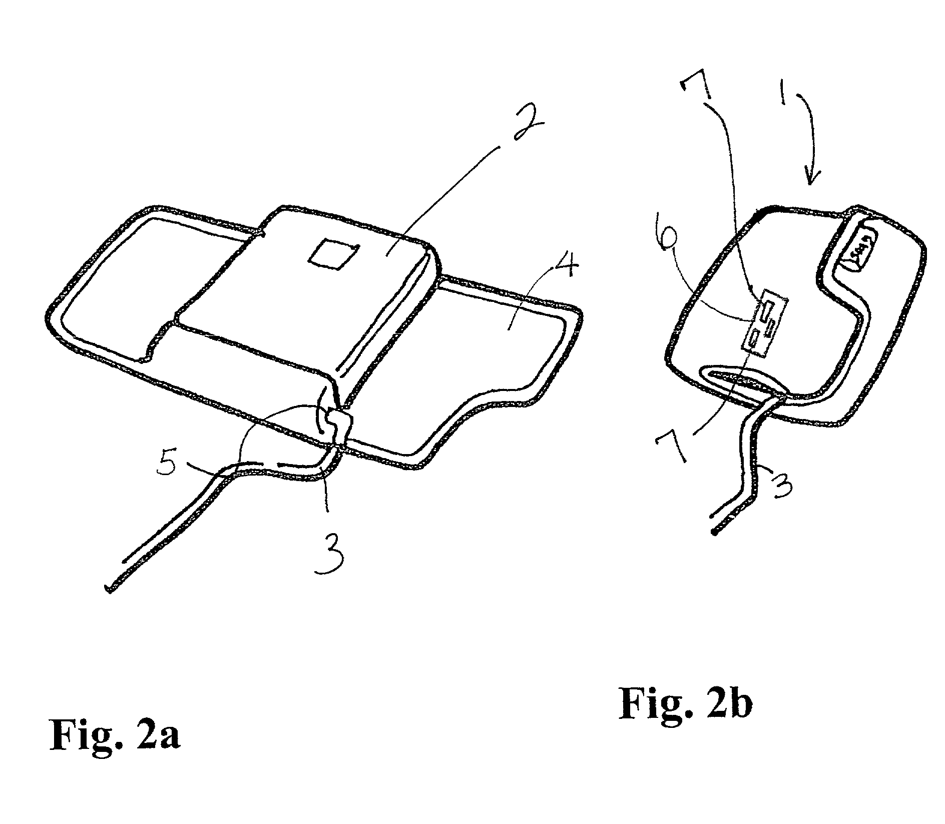
[0022]A carrying case according to a simple embodiment of the present invention is shown in the accepting position in FIG. 2a, and in the enclosing position in FIG. 2b. A portable electronic device is accepted in a pocket portion of the case as shown in FIG. 2a. FIG. 2b shows the case enclosing the electronic device. The case can be held in a closed position using many fastening devices such as a hook and loop fastener member, Velcro, magnetic force, and myriad other known techniques. FIG. 3 shows a snap device ...
PUM
| Property | Measurement | Unit |
|---|---|---|
| Power | aaaaa | aaaaa |
| Water absorption | aaaaa | aaaaa |
| Magnetic force | aaaaa | aaaaa |
Abstract
Description
Claims
Application Information