Two piece punch with pilot hole locator

a pilot hole locator and two-piece technology, applied in the field of improved punches, can solve the problems of insufficient positioning of the hole to be created, added to the cost of the punch assembly, and insufficient locating of the prior art punch assembly, so as to achieve the effect of improving the alignment of the punch

Inactive Publication Date: 2006-01-03
GREENLEE TEXTRON
View PDF27 Cites 24 Cited by
  • Summary
  • Abstract
  • Description
  • Claims
  • Application Information

AI Technical Summary

Benefits of technology

[0008]A primary object of the invention is to provide a punch which improves punch alignment over prior art punches, such as the current difficult to see alignment marks.

Problems solved by technology

One such disadvantage is that the prior art punch assemblies do not provide means for locating the punch assembly in the pilot hole as the punch and the die are drawn together by the draw stud to make a hole in the workpiece.
The alignment marks currently used to align the punch assembly with the pilot hole can be difficult to see by the operator and may allow for error such that the hole to be created may not be properly positioned.
Another disadvantage of prior art punch assemblies is that a significant amount of material is used to manufacture the punch which adds to the expense of the punch assembly.
Yet another disadvantage of the prior art punch assemblies is that the process for forming the punch can be very costly.
An even further disadvantage of the prior art punch assemblies is that the punch is costly to replace as it becomes worn after use.

Method used


Image

  • Two piece punch with pilot hole locator
  • Two piece punch with pilot hole locator
  • Two piece punch with pilot hole locator

Examples


first embodiment

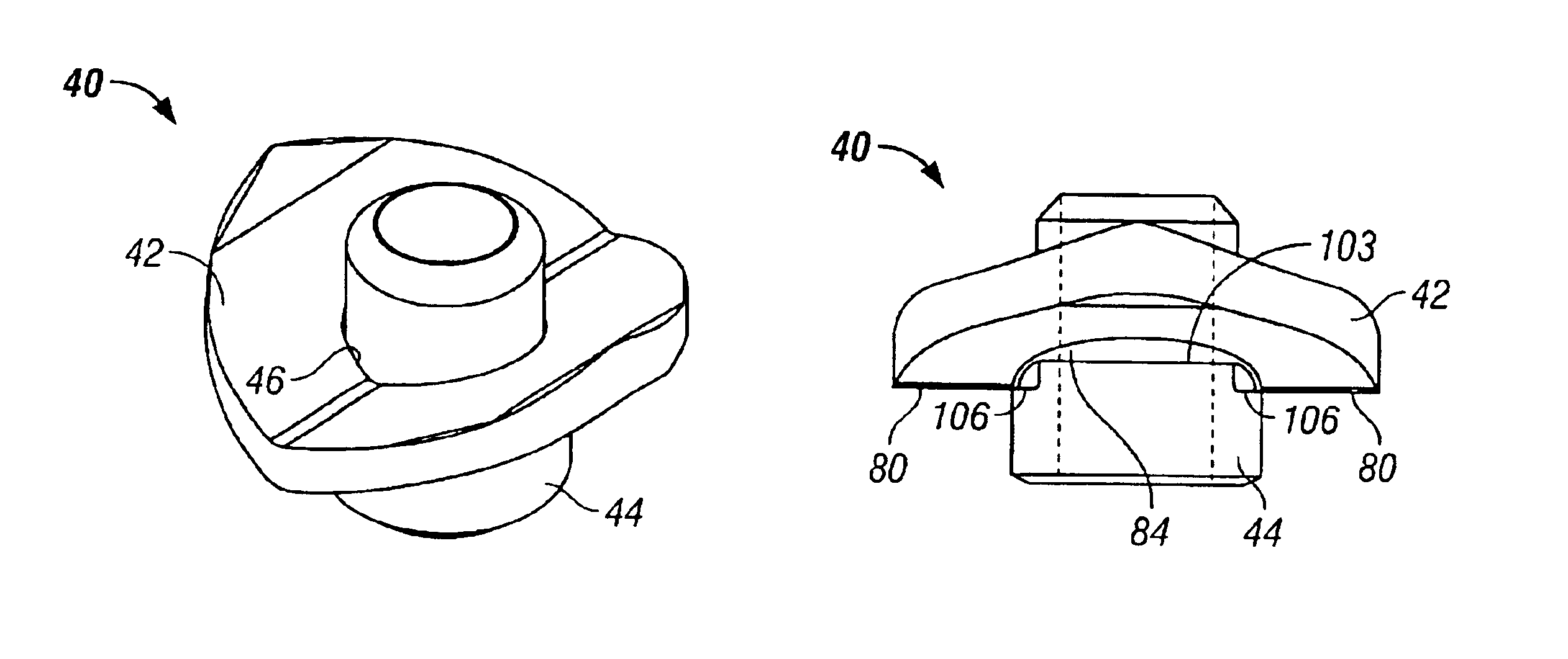
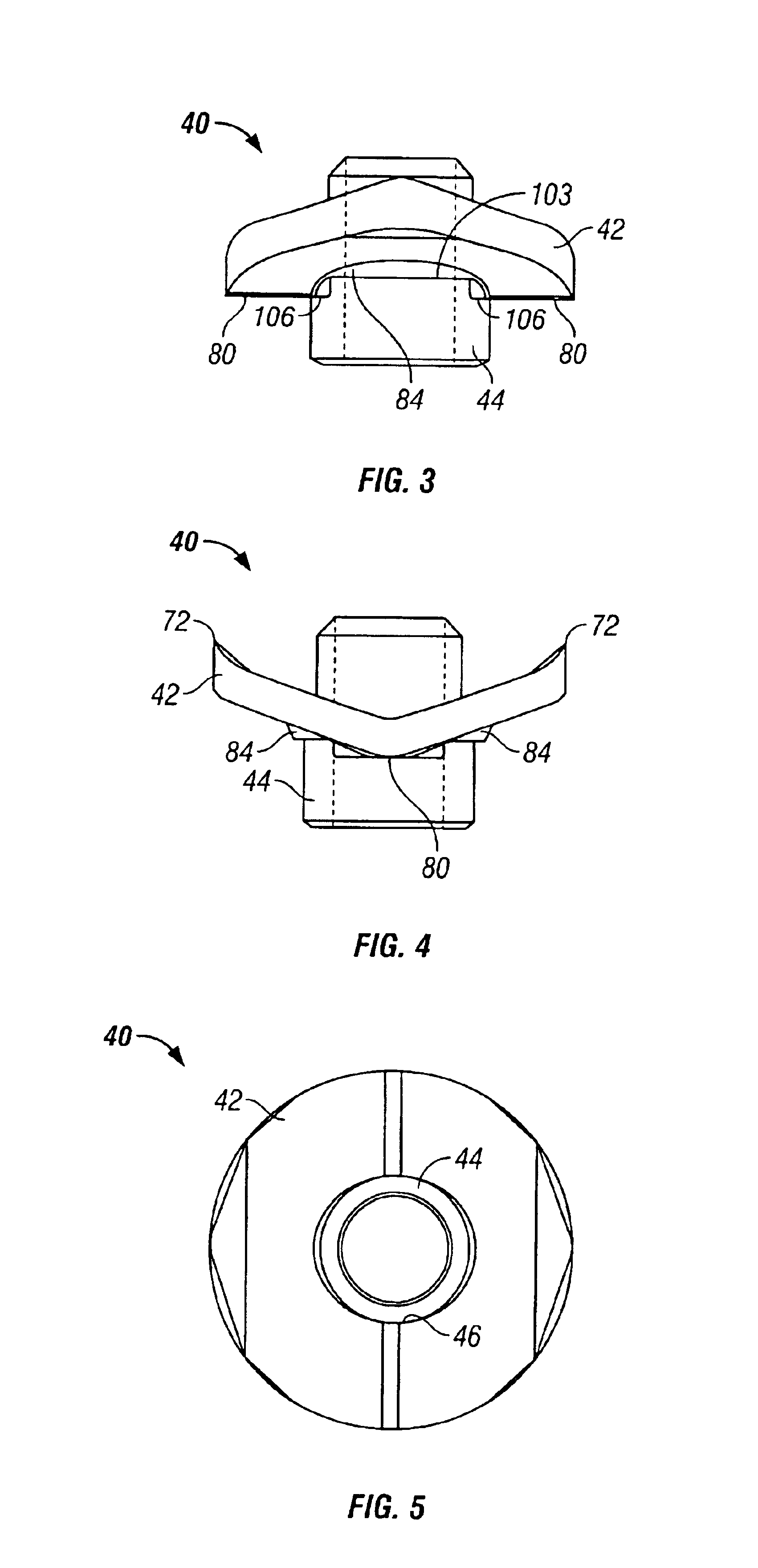
[0036]the cutter 42 is best illustrated in FIGS. 6-9. The cutter 42 generally includes a proximal surface 50, a distal surface 52 and the circular aperture 46. The proximal surface 50 will be positioned proximate the workpiece to be cut. As viewed in a plan view (FIG. 9), the cutter 42 is generally circular. The proximal surface 50 of the cutter 42 includes center surfaces 54, first inclined surfaces 56 and second inclined surface 58.

[0037]As best shown in FIG. 9, the center surfaces 54 extend from opposite sides of the perimeter of the aperture 46 to the perimeter of the proximal surface 50. The first inclined surfaces 56 are generally arch shaped and are diametrically opposed. Each first inclined surface includes an inner edge 64, an outer edge 66, and cutting edges 68. The inner edges 64 of each of the first inclined surfaces 56 are generally C-shaped and abut center surfaces 54 and the aperture 46. Each outer edge 66 is spaced from the aperture 46 and is generally parallel to th...

second embodiment

[0046]the cutter is shown in FIGS. 14-18. The cutter 142 includes a proximal surface 150, a distal surface 152 and a circular aperture 146. The proximal surface 150 will be positioned proximate the workpiece to be cut. As viewed in a plan view (FIG. 17), the cutter 142 is generally circular. The proximal surface 150 of the cutter 142 includes center surfaces 154, first inclined surfaces 156, and second inclined surface 158.

[0047]As best shown in FIG. 17, the center surfaces 154 extend from opposite sides of the perimeter of the aperture 146 to the perimeter of the proximal surface 150. Each first inclined surface 156 includes an inner edge 164, an outer edge 166, and cutting edges 168. The inner edges 164 of each of the first inclined surfaces 156 are generally C-shaped and abut center surfaces 154 and the aperture 146. Each outer edge 166 is spaced from the aperture 146 and is generally parallel to the center surfaces 154. The cutting edges 168 extend along the perimeter of the pro...


PUM

PropertyMeasurementUnit
angleaaaaaaaaaa
angleaaaaaaaaaa
angleaaaaaaaaaa

Abstract

A two piece punch is provided for use in a punch assembly. The punch includes a generally disc shaped cutter and a cylindrically shaped nut. The punch is assembled by passing a portion of the nut through an aperture in the cutter. The punch is mounted to the remainder of the punch assembly by fastening the nut to the draw stud. As the punch becomes worn, use of the nut continues while the cutter is removed and replaced.

Description

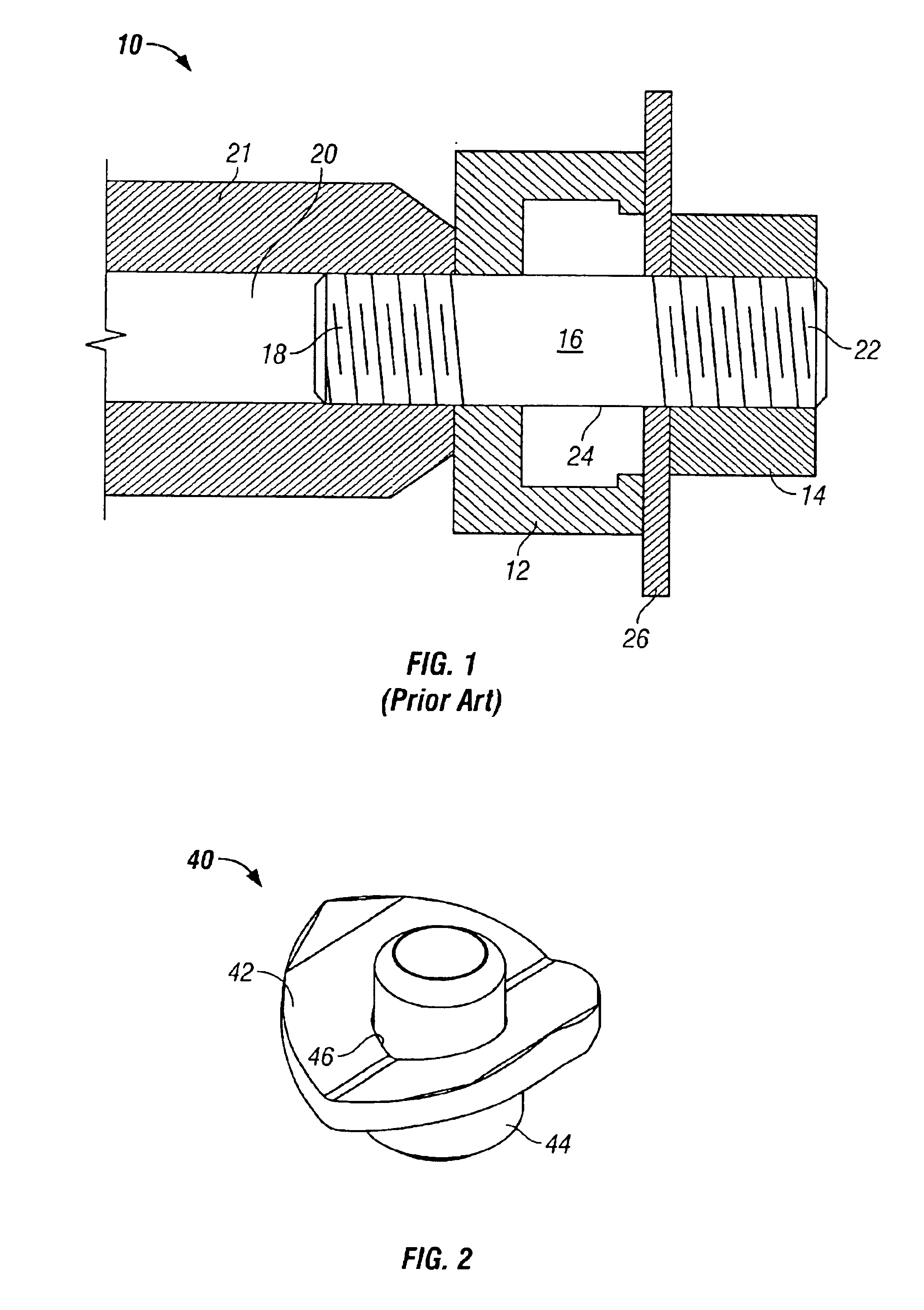
BACKGROUND OF THE INVENTION[0001]The present invention relates to an improved punch which is used in conjunction with a punch driver to punch holes in a work piece, such as for example, sheet metal, aluminum, fiberglass and plastic.[0002]Generally, when a hole is to be punched in a work piece, a small pilot hole is first drilled in the work piece. A punch assembly is then used to create a hole of the desired dimensions in the work piece. A prior art punch assembly 10 is shown in FIG. 1. The punch assembly 10 includes a die 12, a punch 14, and a draw stud 16. A first end 18 of a draw stud 16 is threaded into a ram 20 of a hydraulic punch driver 21. The operator locates the punch assembly 10 in the pilot hole 24 by using “alignment marks”. A second end 22 of the draw stud 16 is inserted through the die 12 and then through the drilled pilot hole 24 in the work piece 26, the draw stud 16 having a circumference that is less than the circumference of the drilled hole 24. The punch 14 is t...

Claims


Application Information

Patent Timeline
Patent Type & Authority Patents(United States)
IPC IPC(8): B26F1/02B21D28/34B26F1/38
CPCB26F1/386B21D28/343Y10T83/9435Y10T83/9425Y10T83/9428
Inventor NORDLIN, WILLIAM F.
Owner GREENLEE TEXTRON
Why Eureka
Try Eureka