Redundant flow control for hydraulic actuator systems

a technology of hydraulic actuators and flow control, which is applied in the direction of fluid couplings, servomotor parallel arrangements, servomotors, etc., can solve the problems of affecting the operation of the system

Active Publication Date: 2006-01-03
HR TEXTRON
View PDF7 Cites 26 Cited by
  • Summary
  • Abstract
  • Description
  • Claims
  • Application Information

AI Technical Summary

Benefits of technology

[0010]A third embodiment may include a method of providing redundant flow control for a hydraulic actuator. Cylinder chamber pressures in both sides of a corresponding actuator may be ported to a corresponding return line in response to failure of a hydraulic flow control system. Flow control may be provided to a corresponding piston of a non-failed hydraulic flow control system. The cylinder chamber pressures in both sides of the corresponding actuator may be ported to the corresponding return line in response to a hydraulic supply line failure and / or an actuator jam. The cylinder chamber pressures may be ported to the return line by moving a bypass-shutoff valve from a shut-off position to a bypass position. The cylinder chamber pressures may be ported to the return line by displacing a bypass control spool from a null position. The displacing of the control spool may include porting a control line to the corresponding return line.

Problems solved by technology

A variety of redundant servoactuators have been used for such safety purposes, however these have often utilized the relatively high system pressures of the hydraulic supply.
Such high pressures can create large bias forces in the chambers of a non-operational piston / cylinder assembly after a single hydraulic system failure, which in turn can make movement of a failed system difficult for an operator and thus may negate advantages of having a redundant actuator system.

Method used


Image

  • Redundant flow control for hydraulic actuator systems
  • Redundant flow control for hydraulic actuator systems
  • Redundant flow control for hydraulic actuator systems

Examples


Embodiment Construction

[0021]The present invention may be understood by the following detailed description, which should be read in conjunction with the attached drawings. The following detailed description of certain embodiments is by way of example only and is not meant to limit the scope of the present invention.

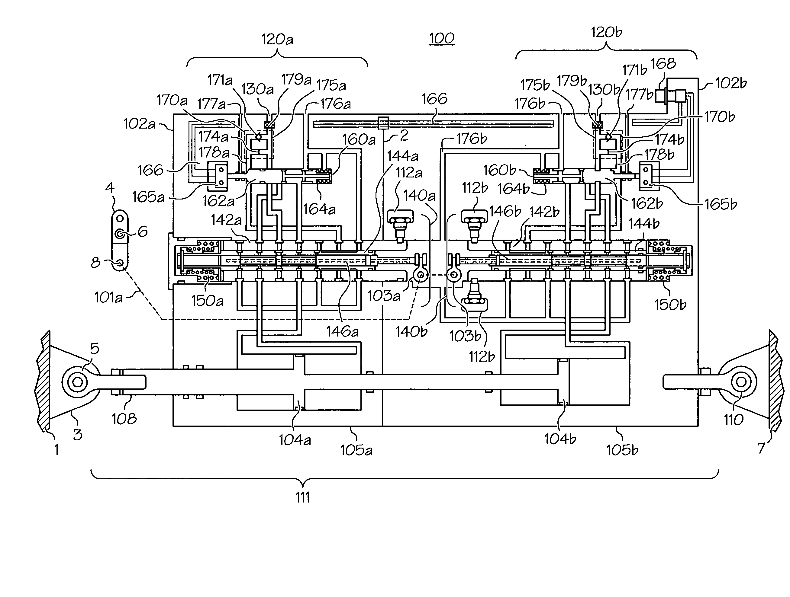
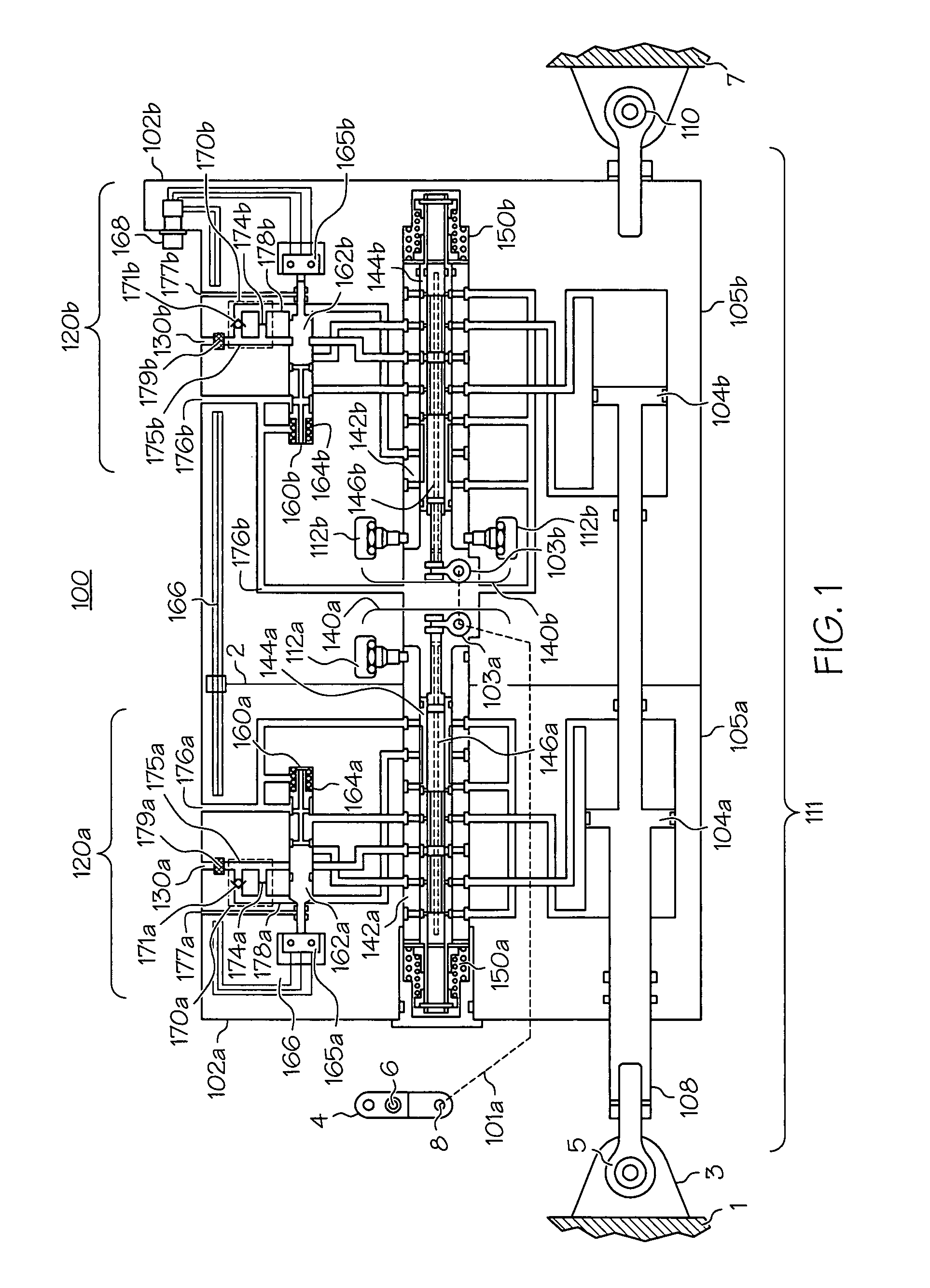
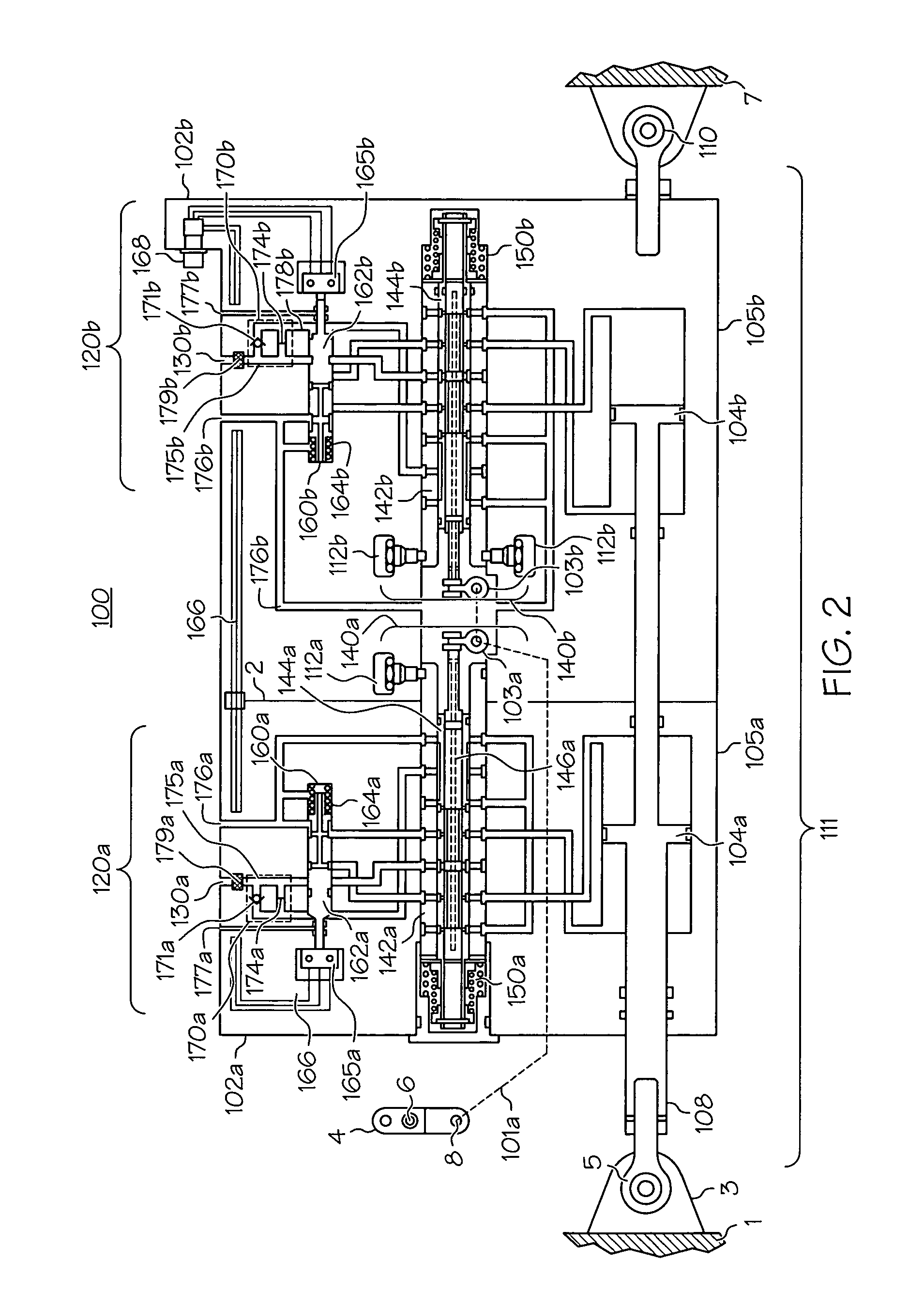
[0022]With reference to FIG. 1, a servoactuator control system or main servo-control system 100 is shown for controlling a dual-tandem hydraulic actuator 111 with a pair of redundant hydraulic flow control systems 120a, 120b. In the drawings, reference characters ending with “a” and “b”, indicate corresponding elements of respective first and second hydraulic flow control systems, e.g., 120a and 120b, except where noted.

[0023]Each hydraulic flow control system 120a, 120b may include a hydraulic flow control valve 140a, 140b, a bypass-shutoff valve assembly 160a, 160b, and a restrictor-check valve assembly 170a, 170b. Each flow control system 120a, 120b may act to control the position of a pisto...


PUM


Abstract

Two or more flow control valves may be used to provide redundant flow control for a hydraulic actuator or servoactuator. The flow control valves include a sleeve, a bypass control spool, and a primary control spool. Under normal operating conditions, each bypass control spool is stationary relative to the sleeve and the flow control valve functions as a four-way hydraulic flow control valve. Each flow control valve is connected to a bypass-shutoff valve including a bypass spool that is moveable from a shut-off position to a bypass position. Upon supply pressure failure to one flow control valve, the bypass spool moves to the bypass position, reducing pressure in the corresponding actuator piston chambers. When a primary control spool becomes jammed, the corresponding bypass control spool moves within its sleeve allowing a bypass groove to port control pressure to the return line, thereby reducing pressure in the corresponding actuator piston chambers.

Description

[0001]This application claims the benefit of U.S. Provisional Application No. 60 / 497,284, filed Aug. 22, 2003, the contents of which are incorporated herein by reference.BACKGROUND[0002]Hydraulic actuators utilize a fluid for the movement of an output element, and these types of actuators are used in a variety of applications including numerous mechanical and aeronautical applications. Hydraulic actuators may be used with hydraulic flow control valves in servomechanisms to control machines and structures, and are sometimes referred to as servoactuators. Servoactuators are commonly used on rotary and fixed-wing aircraft to counter and control the large forces that develop on the flight control surfaces experience during operation of the aircraft. For example, servoactuators may be used in rotary aircraft to position equipment such as a swashplate. Servoactuators may also be used in fixed wing aircraft to position equipment such as nose wheel landing gear, main landing gear, speed bra...

Claims


Application Information

Patent Timeline
Patent Type & Authority Patents(United States)
IPC IPC(8): F15B13/00B64C13/42F15B11/00F15B13/04F15B15/14F15B18/00F15B20/00
CPCB64C13/42F15B13/0403F15B15/1404F15B18/00F15B20/004F15B20/008F15B2211/8757F15B2211/30525F15B2211/7056F15B2211/8633F15B2211/8636F15B2211/864B64C13/505B64C13/503
Inventor HART, KENNETH E.
Owner HR TEXTRON
Why Eureka
Try Eureka