
Dental filling instrument and attachment therefor

Inactive Publication Date: 2006-01-03
MORITA MFG CO LTD
View PDF11 Cites 15 Cited by
  • Summary
  • Abstract
  • Description
  • Claims
  • Application Information

AI Technical Summary

Benefits of technology

[0014]Accordingly, it is an object of the present invention to provide a dental filling instrument capable of filling a tooth cavity with a dental filler more easily and an attachment attachable to the dental filling instrument.

Problems solved by technology

Such conventional filling instruments, however, require application of a large force to the push rod or the lever to extrude the filler.
It is therefore not easy to hold the filling instrument so as not to displace the needle tip from a filler-pouring position even when a larger force is applied to the push rod or lever with a finger.
If the filler is not sufficiently softened, a larger force is required to extrude the filler and, hence, it is difficult to perform the operation of delicately moving the needle tip position as the filler-pouring operation proceeds and the operation of extruding the filler at the same time.
Thus, the conventional instruments require the operator to perform complicated operations while paying attention to many different points.
It is pointed out that such an overflowed filler 9a leads to unsatisfactory convalescence; for example, filler 9a causes a pain when the patient is subjected to percussion or it takes a longer time for filler 9a to be completely absorbed.
If the filler is cooled during the extrusion thereof from the needle, it is possible that the filler cannot be filled closely into a tooth cavity or that the filler adheres to the needle and hence is withdrawn from the tooth cavity along with the needle when the needle is withdrawn from the tooth cavity after the injection of the filler.
Such a cutting operation is difficult if the needle is cool.
Such an exchange makes the filling operation cumbersome.
Further, if instruments used in respective operations are different in size, shape, weight or the like from each other, a feel or touch in one operation is different from that in another operation, making each operation more difficult.
In this case, provision of different filling instruments for respective fillers having different properties raises a problem of cost.
Further, there is a need for adjusting and operating filling instruments respectively, resulting in a cumbersome and complex operation with low efficiency.

Method used


Image

  • Dental filling instrument and attachment therefor
  • Dental filling instrument and attachment therefor
  • Dental filling instrument and attachment therefor

Examples


first embodiment

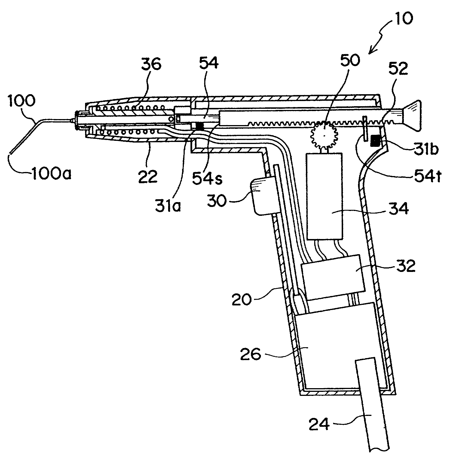
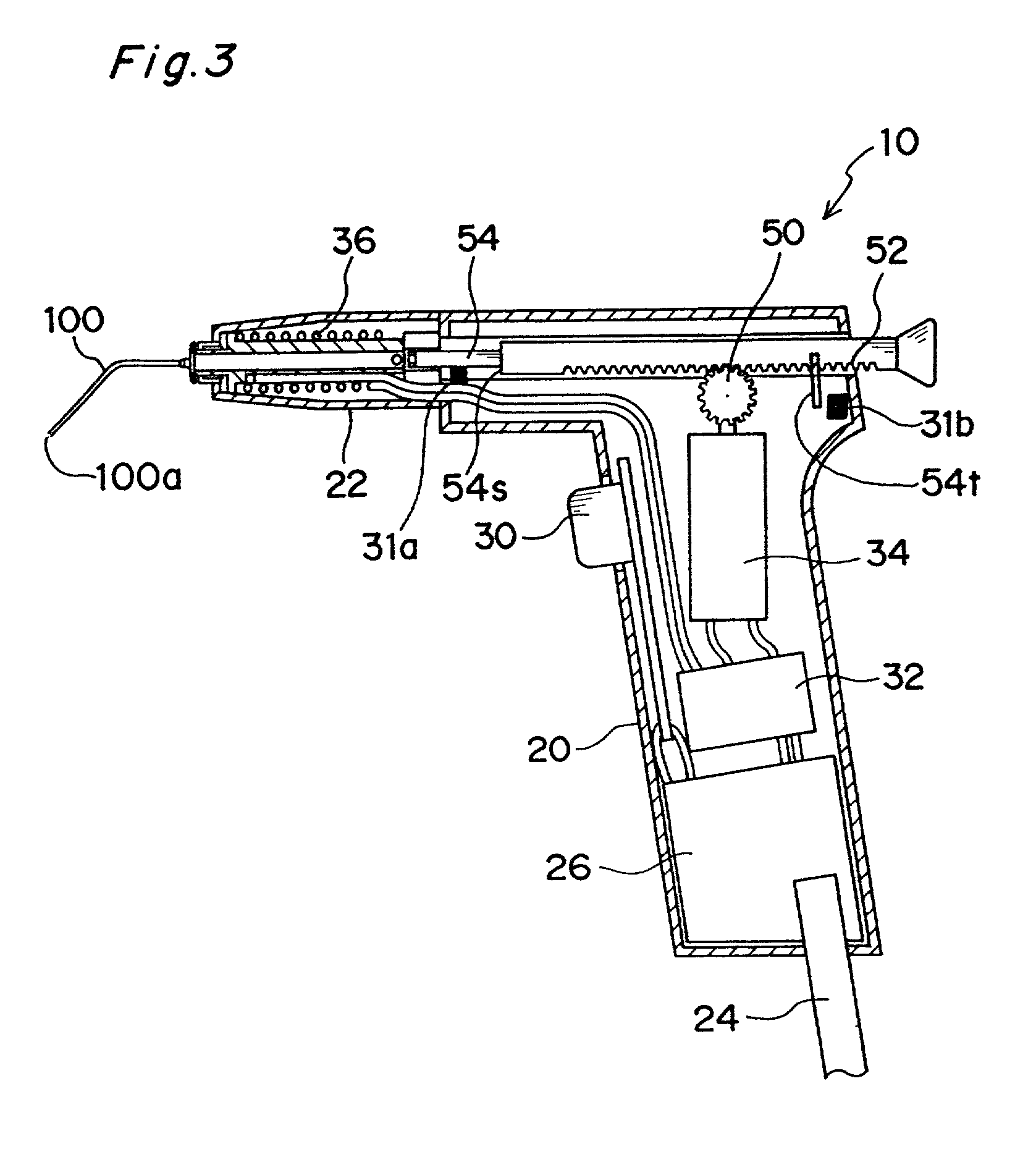
[0101]Referring first to FIG. 3, it is explained about a dental filling instrument 10 of the present invention.

[0102]The dental filling instrument 10 includes a housing 20 substantially gun-shaped so as to allow the user to hold it with one hand, and a needle 100 having a tip 100a from which a dental filler, such as gutta-percha, softened by heating, is extruded when an extruding operation switch 30 is turned ON.

[0103]More specifically, the housing 20 has an upper portion accommodating therein a heater 36 for heating a filler and an extruding shaft 54 for extruding the filler. For heat insulation the heater 36 of the housing 20 is surrounded by a thermal protector 22. The extruding shaft 54 is formed with a rack 52 adapted to mesh with a gear 50 (schematically shown). The housing 20 has a lower portion accommodating therein a motor 34 for driving the gear 50, a control board 32 carrying a control circuit for controlling the heater 36 and the motor 34, the extruding operation switch ...

second embodiment

[0124]Next, with reference to FIGS. 6 to 9F, a dental filling instrument of the present invention is described below.

[0125]The dental filling instrument 14 according to the second embodiment is of substantially the same construction as that of the dental filling instrument 10. The features of the instrument 14 different from those of the instrument 10 are focused in the following description.

[0126]As shown in the sectional view of FIG. 6 and in the enlarged fragmentary view of FIG. 7, the dental filling instrument 14 includes a heater 38 adjacent a needle fitting portion 37. The heater 38, which is separate from and independent of the heater 36 adapted to heat the filler, is adapted to heat the base end of the needle 100. The needle fitting portion 37 allows a spreader- or plugger-type attachment (to be described later) to be fitted thereto instead of the needle 100. It is desirable that the instrument be modified in its outward shape from the substantially T-shaped gun type into a ...

third embodiment

[0134]Next, with reference to FIGS. 10 to 12, a dental filling instrument of the present invention is described below.

[0135]The dental filling instrument according to the third embodiment is of substantially the same construction as that of the first embodiment, but has a different filler magazine.

[0136]Specifically, dental filling instrument 15 shown in FIG. 10 includes a filler magazine 60 slidably supported by an upper portion of the housing 20. The filler magazine 60 has a filler storage sections 62 and 64 in portions outwardly protruding on opposite sides of the housing. When the magazine 60 slides to the right or left in the direction indicated by an arrow 92, the filler in the filler storage section 62 or 64 is introduced into the housing 20 and hence becomes ready to be used in the filling operation.

[0137]For example, it is possible that a filler for filling apical part is stored in the filler storage section 62 on one side while a common filler for filling whole root canal ...


PUM


Abstract

A dental injecting apparatus for injecting a dental filler and a dental tool attached to such a dental injecting apparatus. The apparatus includes: an injection rod for injecting a dental filler; an injection rod driver for performing a dental filler injecting operation that causes the injection rod to move in a dental filler injecting direction by using the force of a power source; and a controller for controlling the dental filler injecting operation of the injection rod driver.

Description

CROSS-REFERENCE TO RELATATED APPLICATION[0001]This application is based upon application No. 2000-341822 filed in Japan, the contents of which are hereby incorporated by reference.BACKGROUND OF THE INVENTION[0002]1. Field of the Invention[0003]The present invention relates to a dental filling instrument and an attachment therefor, and particularly relates to a dental filling instrument used to inject a filler into a tooth cavity in dental treatment and an attachment that can be attached to the dental filling instrument.[0004]2. Description of the Related Arts[0005]Heretofore, various dental filling instruments for injecting a dental filler such as gutta-percha or resin into a tooth cavity (such as a root canal or a defective part of a tooth) have been proposed for dental treatment.[0006]Japanese Examined Laid-Opened Patent Publication No. HEI 1-40621 (International Publication Number: WO82 / 03761, International Application Number: PCT / US81 / 00589), for example, discloses a syringe-typ...

Claims


Application Information

Patent Timeline
IPC IPC(8): A61C5/02A61C5/04A61C3/08A61C5/06
CPCA61C5/04B05C17/00593A61C5/062A61C5/045B05C17/00516A61C5/50A61C5/55A61C5/62
Inventor OKAWA, SHINICHIMATOBA, KAZUNARIKOBAYASHI, CHIHIROYOSHIOKA, TAKATOMO
Owner MORITA MFG CO LTD
Learn More