Dental attachment assembly and method

Inactive Publication Date: 2006-01-03
ZEST IP HLDG
View PDF32 Cites 56 Cited by
  • Summary
  • Abstract
  • Description
  • Claims
  • Application Information

AI Technical Summary

Benefits of technology

[0009]The retention portions may be of the same diameter. However, in an exemplary embodiment of the invention, the uppermost retention portion closest to the first end of the male member has a diameter which is slightly less than that of the lower retention portion or portions. This will allow the female member to snap over the first rib with less force required, allowing for easier seating of the attachment by the patient. The lowest rib or retention portion is of slightly greater diameter to have more retentive hold than the or each rib above it, thus holding the denture more securely in place against accidental dislodgement. This arrangement will make the denture easier to insert or place than to remove.
[0010]In an exemplary embodiment of the invention, a cap or housing secured in the dental appliance pivots over the female or retention member. The cap has an inner curved surface for snap engagement over the outer surface of the female or retention member, retaining the female member and preventing it from accidentally coming out as the denture is removed. The curvature is such that the female member can be relatively easily inserted into the cap, but, once inserted, the female member is held tight against accidental removal.
[0011]In one embodiment of the invention, the male or abutment member is designed for distal attachment to an adjacent tooth, rather than co-axial attachment to an underlying tooth root or implant

Problems solved by technology

However, users may find it difficult to properly locate the male head in the female socket, such that the head may hit the periphery of the socket in some cases.
Repeated impacts of this nature may damage the retentive head o

Method used


Image

  • Dental attachment assembly and method
  • Dental attachment assembly and method
  • Dental attachment assembly and method

Examples


Example

DETAILED DESCRIPTION OF THE DRAWINGS

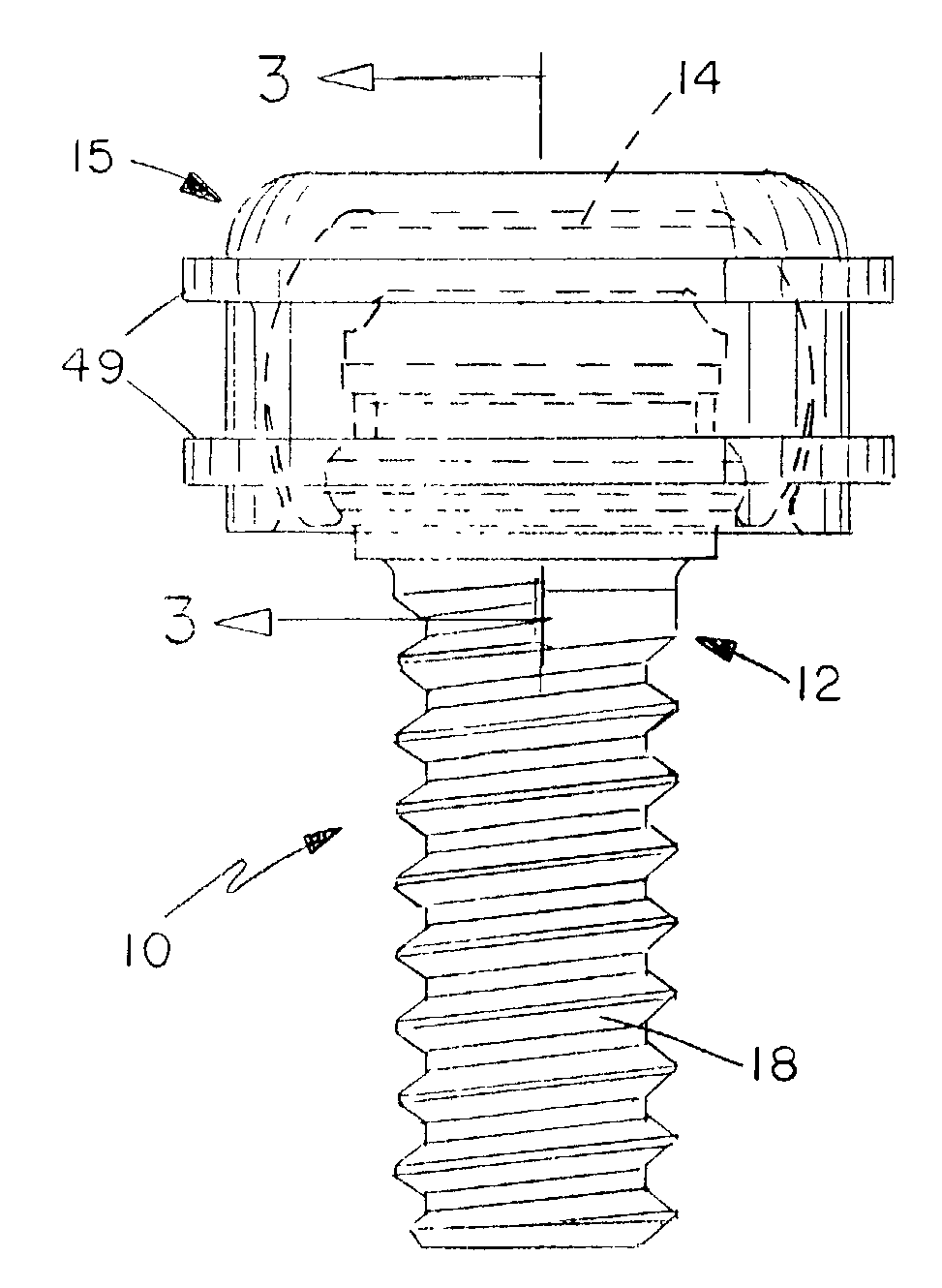
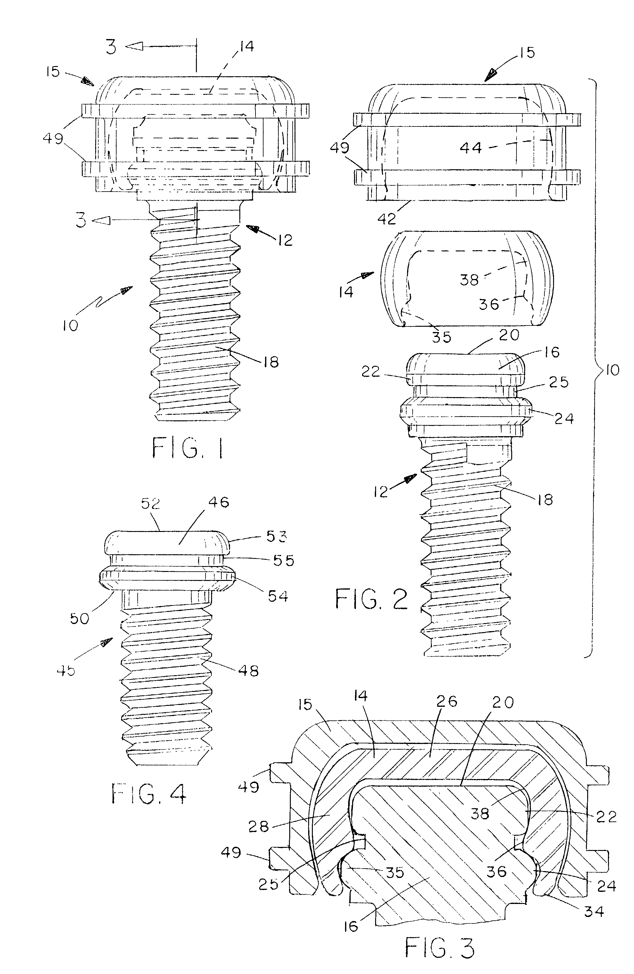
[0023]FIGS. 1 to 3 illustrate a dental attachment or anchor assembly 10 securing a dental appliance such as a partial denture to a remaining non-vital root. The assembly 10 basically comprises a male or abutment member 12, a female or retention member 14, and a cap 15 for securing in a suitable indent in the denture. The male member 12 will be of a suitable strong metal material such as stainless steel with titanium nitride coating, while the female member is of a material having some resilience, such as nylon, and the cap is of metal such as stainless steel.

[0024]The male or abutment member 12 has an enlarged head 16 and a threaded shaft or stem 18 extending from the head for attachment in a prepared bore in a tooth root in a conventional manner, for example as described in our prior U.S. Pat. No. 6,299,447, the contents of which are incorporated herein by reference. The head 16 has an upper end 20 and an outer locating surface having first and s...


PUM


Abstract

A dental attachment assembly has an abutment member for attachment to a tooth root, implant, adjacent tooth, or bar, and a retention member for hinged engagement in a cap secured in a dental appliance. A skirt projects from one end of the cap for releasable snap engagement over an outer locating surface on the abutment member. The outer locating surface has at least two axially spaced retention surfaces for mating, snap engagement with corresponding spaced snap engagement formations on the inner surface of the cap, to provide a stacked, external retention between the abutment and retention members.

Description

BACKGROUND OF THE INVENTION[0001]The present invention relates to a dental attachment or anchoring structure for attaching a dental appliance such as a full denture, overdenture, partial denture, or the like to a remaining non-vital root, an adjacent tooth, or to an endosseus implant.[0002]Dental anchoring assemblies are known in which a female part is provided for attachment to a root, implant, or adjacent tooth, and a male part is engaged in a recess in a dental appliance, the male and female parts having mating, snap engageable formations for releasably securing the male part to the female part. For example, in U.S. Pat. No. 5,417,570 of Zuest, the female part has a socket and the male part has a head for snap engagement in the socket. However, users may find it difficult to properly locate the male head in the female socket, such that the head may hit the periphery of the socket in some cases. Repeated impacts of this nature may damage the retentive head of the male, causing it ...

Claims


Application Information

Patent Timeline
IPC IPC(8): A61C13/225A61C8/00A61C13/265
CPCA61C13/2656A61C8/0048A61C8/00
Inventor MULLALY, SCOTTZUEST, PAUL T.
Owner ZEST IP HLDG
Why Eureka
Try Eureka