Object identification system with adaptive transceivers and methods of operation

a technology of object identification and transceiver, applied in the field of communication systems, can solve problems such as interference with response, and achieve the effects of facilitating wider-band reception, enhanced transceiver communication, and enhanced transceiver communication

Inactive Publication Date: 2006-01-03
RF CODE +1
View PDF25 Cites 76 Cited by
  • Summary
  • Abstract
  • Description
  • Claims
  • Application Information

AI Technical Summary

Benefits of technology

[0008]The monitor may further include a first antenna coupled to the first transmitter and a squelch circuit for dissipating energy on the antenna after lapse of the first duration and before receiving from the first receiver the response signal from the resonant circuit. By quickly dissipating energy, the response signal may be more quickly and accurately received by the second receiver and consequently the second frequency may be more quickly and accurately determined, increasing system sensitivity and reliability. Obtaining quicker receiving from the second receiver extends the operating range of the monitor or permits operation with weaker signals. Weaker signals may originate from transceivers located further from the monitor or in an orientation that is detrimental to reception by the first receiver. Such detrimental orientation of the antenna in the transceiver may be with respect to the first antenna of the monitor or with respect to other transceivers proximate to the transceiver antenna.
[0026]A carrier in one implementation according to various aspects of the present invention includes an antenna and a series capacitor for tuning the antenna. Enhanced transceiver communication results when transceivers are placed in the carrier. In an alternate implementation, a carrier includes a first and a second antenna each with a respective tuning capacitor. The first and the second antenna are coupled to cooperate. Energy received in a first pattern is re-radiated in second pattern for further enhanced transceiver communication.

Problems solved by technology

Transceivers of the type having a resonant circuit coupled to an antenna, when operating in close proximity to each other, may interfere with the response from a single transceiver by absorbing the energy intended to be received by the transceiver, absorbing the energy transmitted by the transceiver, or altering the resonant frequency of the resonant circuit.
Weaker signals may originate from transceivers located further from the monitor or in an orientation that is detrimental to reception by the first receiver.
Such detrimental orientation of the antenna in the transceiver may be with respect to the first antenna of the monitor or with respect to other transceivers proximate to the transceiver antenna.

Method used


Image

  • Object identification system with adaptive transceivers and methods of operation
  • Object identification system with adaptive transceivers and methods of operation
  • Object identification system with adaptive transceivers and methods of operation

Examples


Embodiment Construction

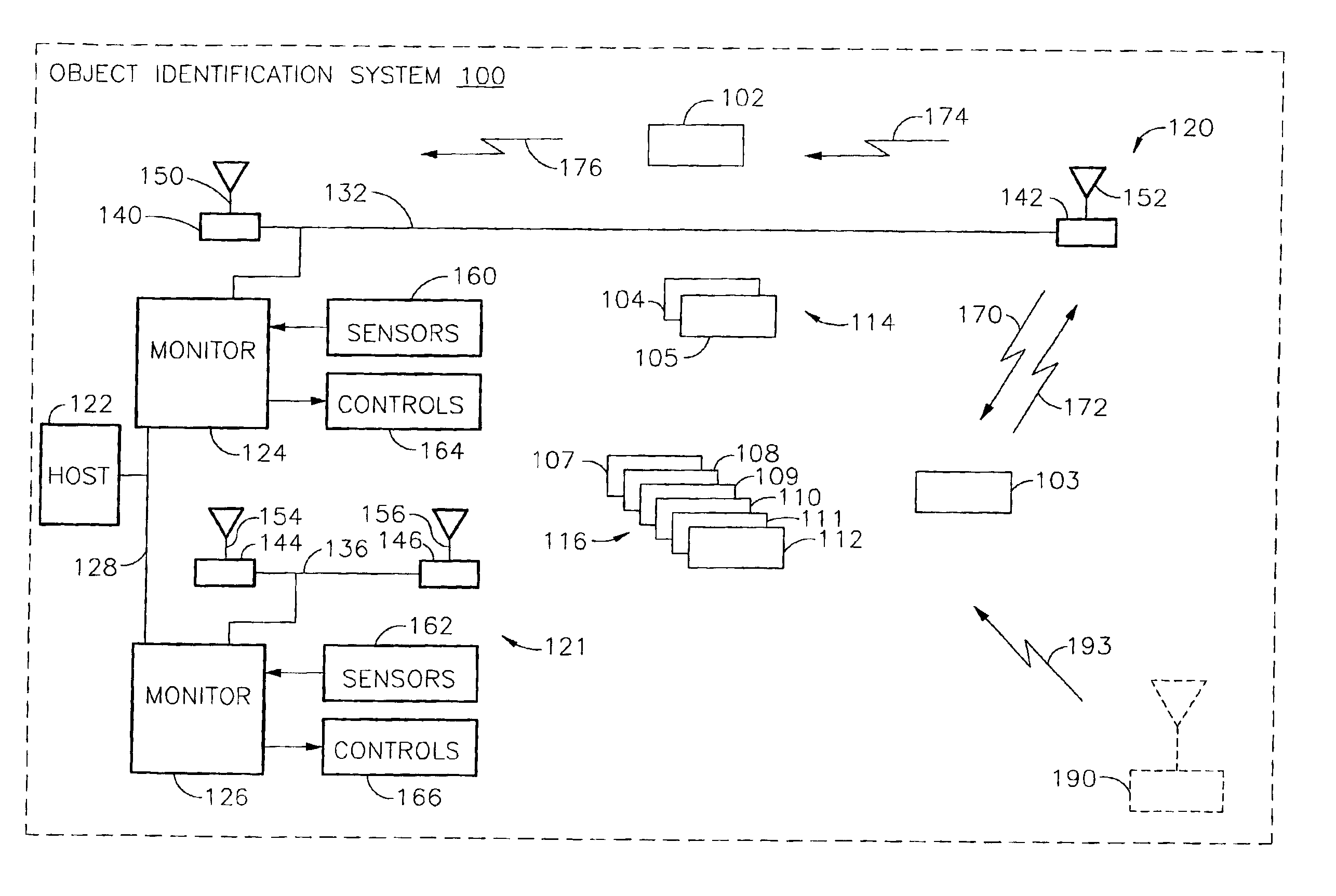
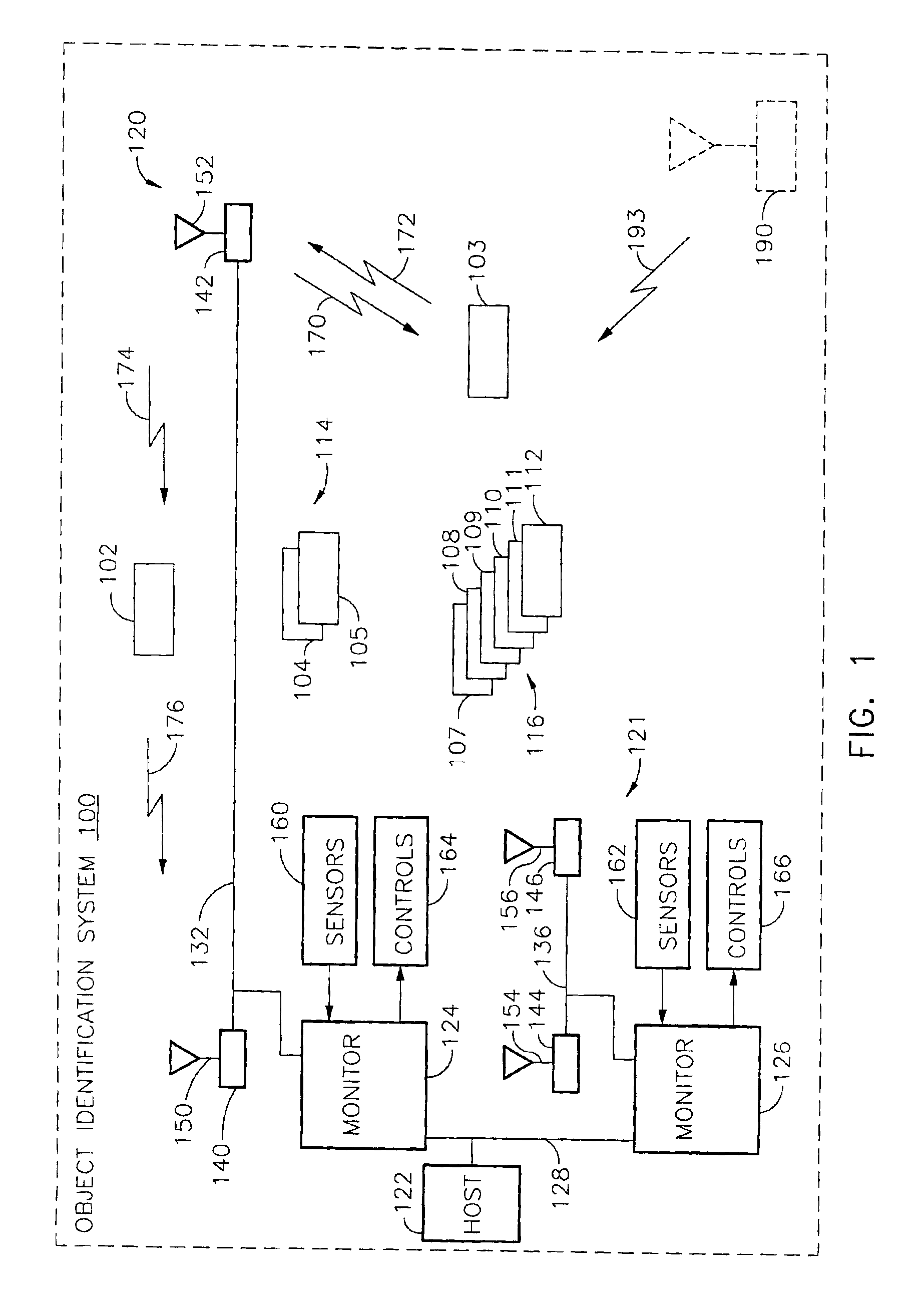
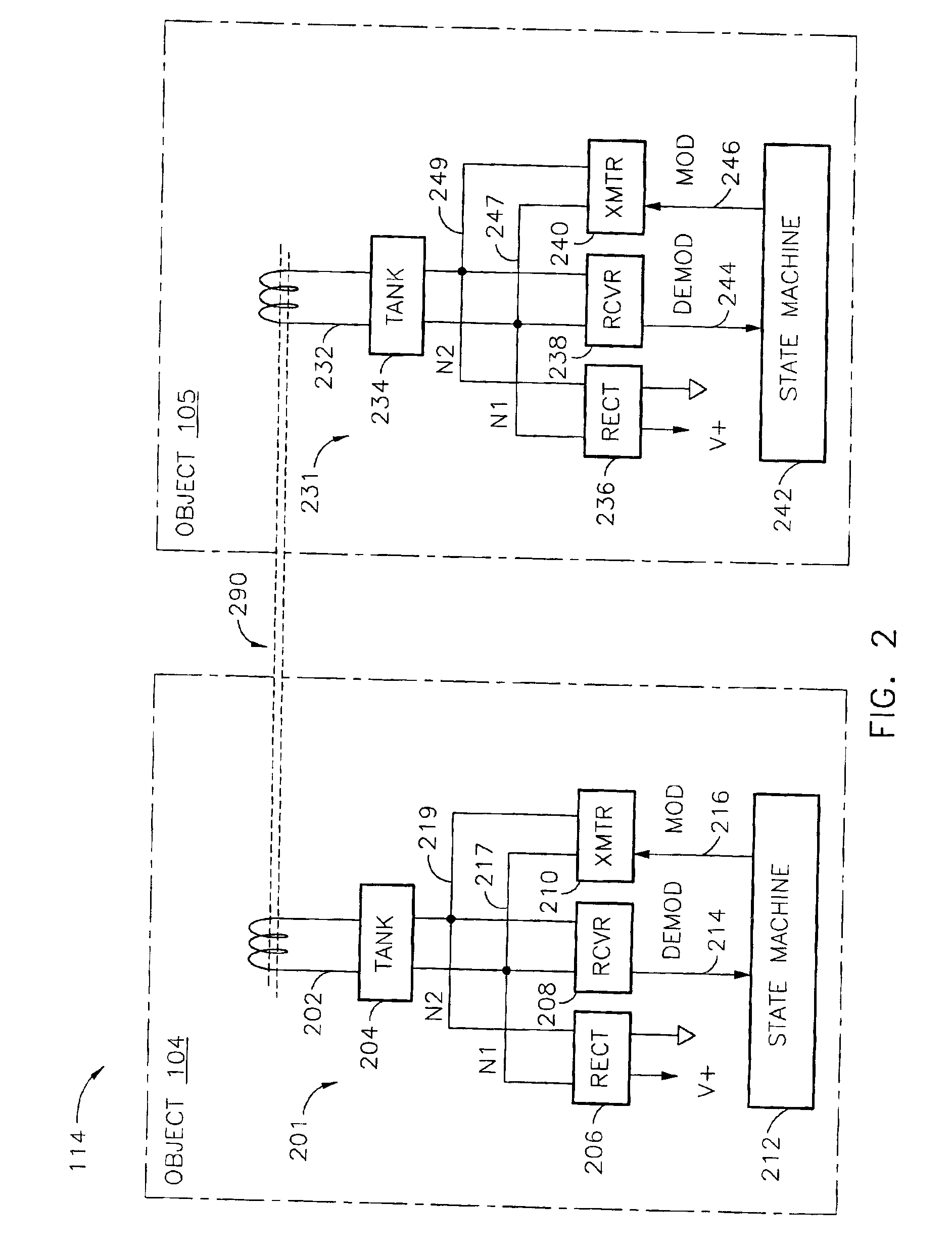
[0066]An object identification system, according to various aspects of the present invention, provides communication between a monitor and an object, while the monitor and object are within communicating range. Each object includes a resonant circuit coupled to an antenna used for communication. Communication, as used herein, may be used to accomplish one or more purposes including: (a) to detect presence of a resonant circuit (e.g., to locate an object as in a zone), (b) to provide operative power to a transceiver, (c) to determine the resonant frequency of such a resonant circuit, (d) to determine a transceiver identification, (e) to receive data from a transceiver, or (f) to send data to one or more transceivers. Transmitted power levels may vary according to the range suitable for the communication. For example, objects may be detected at a higher transmitted power level and a warning issued that some objects may be out of range for interrogation. Communication may be accomplish...


PUM


Abstract

An object identification system includes a monitor and a plurality of transceivers that communicate over a common medium. The monitor includes a first transmitter, a first receiver, and a processor. Each transceiver includes a resonant circuit, a transmitter, a receiver, and an antenna coupled to the resonant circuit. The processor performs a method for performing transceiver communication that includes the steps of: (a) transmitting from the first transmitter a first frequency for a first duration; (b) after lapse of the first duration, receiving via the first receiver a response signal from at least one of the resonant circuits; (c) determining a second frequency from the received response signal; and (d) performing transceiver communication using the second frequency. Transceivers of the type having a resonant circuit coupled to an antenna, when operating in close proximity to each other, may interfere with the response from a single transceiver by absorbing the energy intended to be received by the transceiver, absorbing the energy transmitted by the transceiver, or altering the resonant frequency of the resonant circuit. By determining the second frequency for transceiver communication, the monitor may establish communication with the single transceiver at a frequency better suited for transferring operative power to the transceiver, conducting an interrogation protocol for identifying the transceiver, or for data transfer.

Description

CROSS-REFERENCE TO RELATED APPLICATIONS[0001]This application is a Divisional application of, and claims priority from, U.S. patent application Ser. No. 09 / 372,274 by Rodgers, et al., filed Aug. 11, 1999 now U.S. Pat. 6,362,737, which is a Continuation-In-Part application of, and claims priority from U.S. patent application Ser. No. 09 / 233,755 by Rodgers, et al., filed on Jan. 20, 1999 now U.S. Pat. 6,351,215, which is a Continuation-In-Part application of U.S. patent application Ser. No. 09 / 088,924, by Rodgers, et. al, filed on Jun. 2, 1998, now abandoned. These related applications are incorporated herein by reference.FIELD OF THE INVENTION[0002]Embodiments of the present invention relate to communication systems of the type having multiple transmitting and receiving devices that share a common communication medium; and, to methods for establishing communication in the presence of large numbers of such devices.BACKGROUND OF THE INVENTION[0003]Conventional data communication system...

Claims


Application Information

Patent Timeline
Patent Type & Authority Patents(United States)
IPC IPC(8): G08B13/14G01S19/25G01S5/14G01S13/75G01S19/48G01V15/00G06K7/00G06K7/08G06K7/10G06K17/00G06K19/07H01Q1/22H01Q1/38H01Q5/00H01Q5/35H01Q5/40H01Q7/00H01Q21/28H01Q23/00H04B1/59H04B5/02
CPCH01Q7/00H01Q5/40H01Q21/28H01Q23/00G01S13/753G01S13/756G01S13/758G06K7/0008G06K7/10039G06K7/10336G06K7/10346G06K19/0701G06K19/0723G06K19/0724G06K19/07779G06K19/07783G08B13/2417H01Q1/22H01Q1/2225H01Q1/38H01Q5/35H01Q9/14
Inventor RODGERS, JAMES L.COULTHARD, JOHN J.FOWLER, BILLY C.JAECKS, HOWARD K.LASTINGER, ROC A.PICARD, PAUL A.REHMAN, MOHAMMAD A.
Owner RF CODE
Why Eureka
Try Eureka