Lead with terminal connector assembly

a terminal connector and assembly technology, applied in the field of implantable leads, can solve the problems of unnecessarily draining the battery, floating electrodes can require increased voltage, and the electrical performance of these electrodes is generally less than optimal, so as to improve the ease of manufacturability, reduce the cost of through put, and reduce the cos

Inactive Publication Date: 2006-01-03
CARDIAC PACEMAKERS INC
View PDF557 Cites 43 Cited by
  • Summary
  • Abstract
  • Description
  • Claims
  • Application Information

AI Technical Summary

Benefits of technology

[0018]In yet another embodiment, a system includes an electronics system which has a pulse generator. The pulse generator is electrically coupled with a lead which includes a lead body extending from a distal end to a proximal end. At least one conductor is disposed within the lead body and extends from the distal end to the proximal end of the lead body. An outer terminal ring is coupled with the lead body, and a sleeve is coupled with the outer terminal ring, and is also coupled with a terminal pin. The coupling allows for rotational movement between the outer terminal ring and the terminal pin. The sleeve is coupled with the outer terminal ring or the terminal pin with a snap-fit coupling. The snap-fit coupling, in one embodiment, comprises a first and second set of cantilevered hooks. In another embodiment, the snap-fit coupling comprises an annular flange received in a recess. In another embodiment, the snap-fit coupling includes a ring latch received in a recess and a pin latch which folds about a hinge point. In yet another embodiment, the lead further includes a movement assembly which is configured to extend and retract an active fixation mechanism. The movement assembly includes a housing having an internally threaded portion and an externally threaded collar which is engaged with the internally threaded portion. In another embodiment, the movement assembly further includes an internally threaded insert disposed within the lead, where the threaded collar is engaged with the threaded insert.
[0019]The lead assembly described above provides several advantages, for example, ease of manufacturability is increased and through put times are reduced. The individual components can be snapped together, as opposed to waiting for messy bonding or long cure times. Bonding blocks, used for the bonding process, are eliminated, which are expensive, difficult and costly to clean. A consistent and increased strength of coupling is achieved using the snap fit design since bonding is variable based on the operator. Yet another advantage is that the geometry of the snap fit connector provides an insulation with a known thickness, which allows for a repeatable dielectric strength.

Problems solved by technology

Since the location of floating electrodes is not fixed with respect to the endocardial wall, the electrical performance of these electrodes varies and is generally less than optimal.
In addition, the floating electrodes can require increased voltage which unnecessarily drains the battery.
With passive fixation elements, it can be difficult to determine whether the lead will affix in the location at which it is implanted.
As the stylet is rotated however, the active fixation element may jump out of the end of the lead and damage tissue, and / or the helix.
In addition, it is difficult for the implanter to determine how many turns to the stylet is necessary to advance the helix a certain distance.
However, the process of using medical adhesive is timely and costly.
In addition, the medical adhesive bonds inconsistently, sometimes resulting in mechanical and electrical separation between the components.

Method used


Image

  • Lead with terminal connector assembly
  • Lead with terminal connector assembly
  • Lead with terminal connector assembly

Examples


Embodiment Construction

[0054]In the following detailed description, reference is made to the accompanying drawings which form a part hereof, and in which is shown by way of illustration specific embodiments in which the invention may be practiced. These embodiments are described in sufficient detail to enable those skilled in the art to practice the invention, and it is to be understood that other embodiments may be utilized and that structural changes may be made without departing from the scope of the present invention. Therefore, the following detailed description is not to be taken in a limiting sense, and the scope of the present invention is defined by the appended claims and their equivalents.

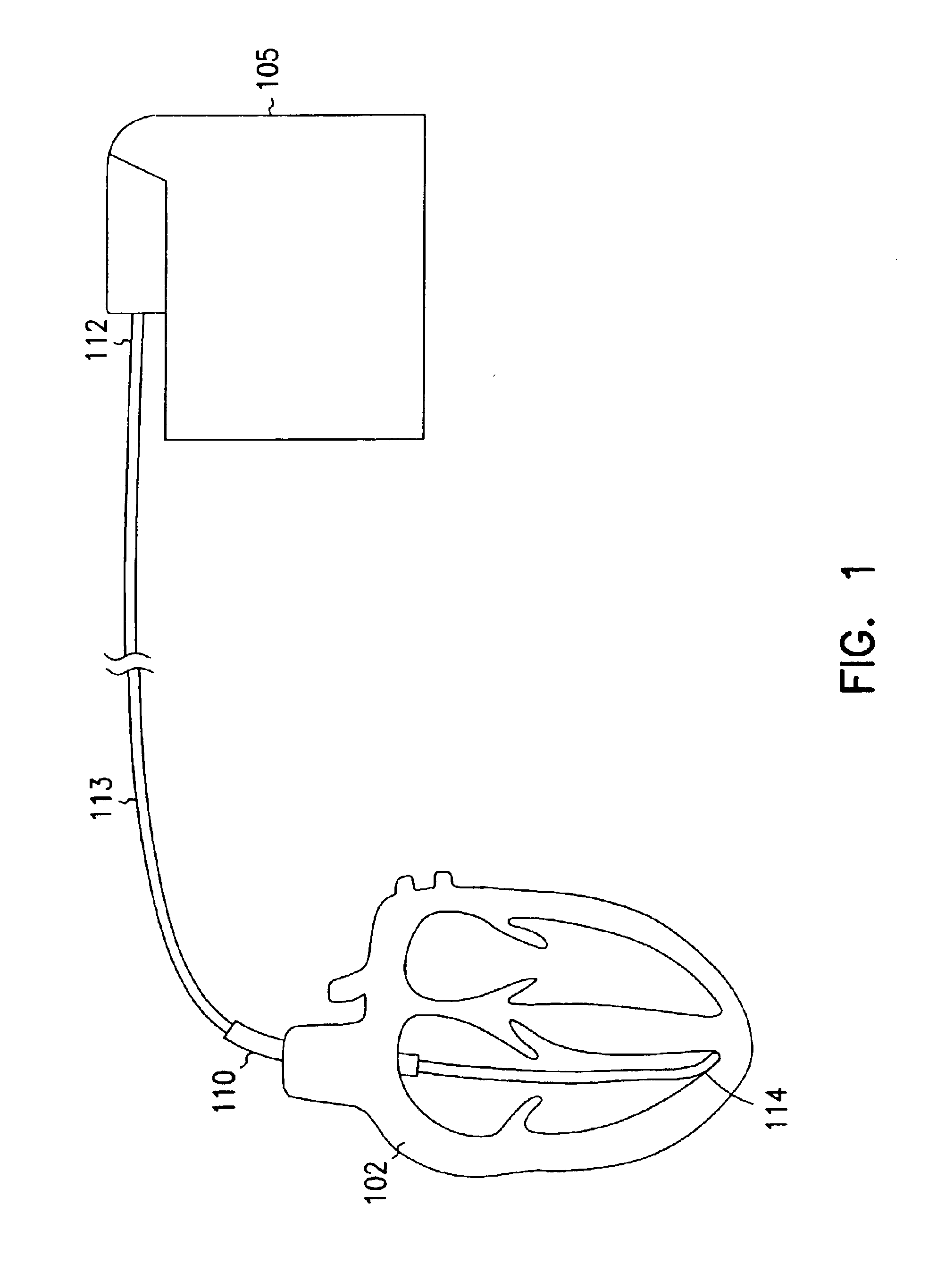
[0055]An extendable and retractable lead 110 and lead system 100 are illustrated in FIG. 1. FIG. 1 is a block diagram of a system 100 for delivering and / or receiving electrical pulses or signals to stimulate and / or sense the heart 102. The system 100 includes a pulse generator 105 and a lead 110. The pulse gen...


PUM

PropertyMeasurementUnit
tensile strengthaaaaaaaaaa
temperatureaaaaaaaaaa
anti-rotationaaaaaaaaaa

Abstract

A lead includes a lead body extending from a distal end to a proximal end, and at least one conductor disposed within the lead body and extending from the distal end to the proximal end of the lead body. The lead further includes an outer terminal ring, a terminal pin, and an insulative sleeve disposed between the outer terminal ring and the terminal pin, where the insulative sleeve is coupled with the outer terminal ring with a snap-fit connection. A pin latch is disposed on an outer periphery surface of the insulative sleeve, where the pin latch is rotatable about a hinge point.

Description

CROSS-REFERENCE TO RELATED APPLICATIONS[0001]This patent application is a division of U.S. patent application Ser. No. 09 / 472,098, filed on Dec. 23, 1999 now U.S. Pat. No. 6,501,990, which is a continuation-in-part of U.S. patent application Ser. No. 09 / 359,580, filed on Jul. 22, 1999 now U.S. Pat. No. 6,463,334, which is a continuation-in-part of U.S. patent application Ser. No. 09 / 121,005, filed on Jul. 22, 1998, now issued as U.S. Pat. No. 6,141,594; U.S. patent application Ser. No. 09 / 120,824, filed on Jul. 22, 1998, now issued as U.S. Pat. No. 6,212,434; and U.S. patent application Ser. No. 09 / 184,226, filed on Nov. 2, 1998, now abandoned, the specifications of which are incorporated herein by reference in their entirety.FIELD OF THE INVENTION[0002]The present invention relates generally to implantable leads. More particularly, it pertains to leads having an extendable and retractable fixation mechanism.BACKGROUND OF THE INVENTION[0003]Electrodes have been used to stimulate con...

Claims


Application Information

Patent Timeline
Patent Type & Authority Patents(United States)
IPC IPC(8): A61N1/05A61B5/0408A61N1/375
CPCA61N1/056A61N1/0563A61N1/0573A61N1/3752Y10T29/49217Y10T29/49204Y10T29/49208
Inventor LEY, GREGORY R.ZAREMBO, PAUL E.
Owner CARDIAC PACEMAKERS INC
Why Eureka
Try Eureka