Depth control mechanism

a control mechanism and depth gauge technology, applied in the field of depth gauge systems, can solve the problems of easy loss of loose parts, difficult manipulation of threaded and gear types, and high adjustment time of threaded and gear types, and achieve the effects of easy maintenance, low cost, and durable construction

Active Publication Date: 2006-01-10
BLUE LEAF I P +1
View PDF7 Cites 24 Cited by
  • Summary
  • Abstract
  • Description
  • Claims
  • Application Information

AI Technical Summary

Benefits of technology

[0017]It is a still further object of the instant invention to provide a depth control mechanism that is durable in construction, inexpensive to manufacture, carefree of maintenance, facile in assemblage, and simple and effective in use.
[0018]These and other objects are obtained by providing a depth control mechanism t

Problems solved by technology

The threaded and gear types require much time to adjust from one end of the range to the other end, and with use often become very hard to manipulate because of corrosion.
Most pin and clip types have loose parts which are easily lost and are also

Method used


Image

  • Depth control mechanism
  • Depth control mechanism
  • Depth control mechanism

Examples


Embodiment Construction

[0025]Many of the fastening, connection, processes and other means and components utilized in this invention are widely known and used in the field of understanding and use of the invention by a person skilled in the art, and they will not therefore be discussed in significant detail. Also, any reference herein to the terms “left” or “right” are used as a matter of mere convenience, and are determined by standing at the rear of the mechanism facing in its normal direction of travel. Furthermore, the various components shown or described herein for any specific application of this invention can be varied or altered as anticipate by this invention and the practice of a specific application of any element may already be widely known or used in the art by persons skilled in the art and each will likewise not therefore be discussed in significant detail.

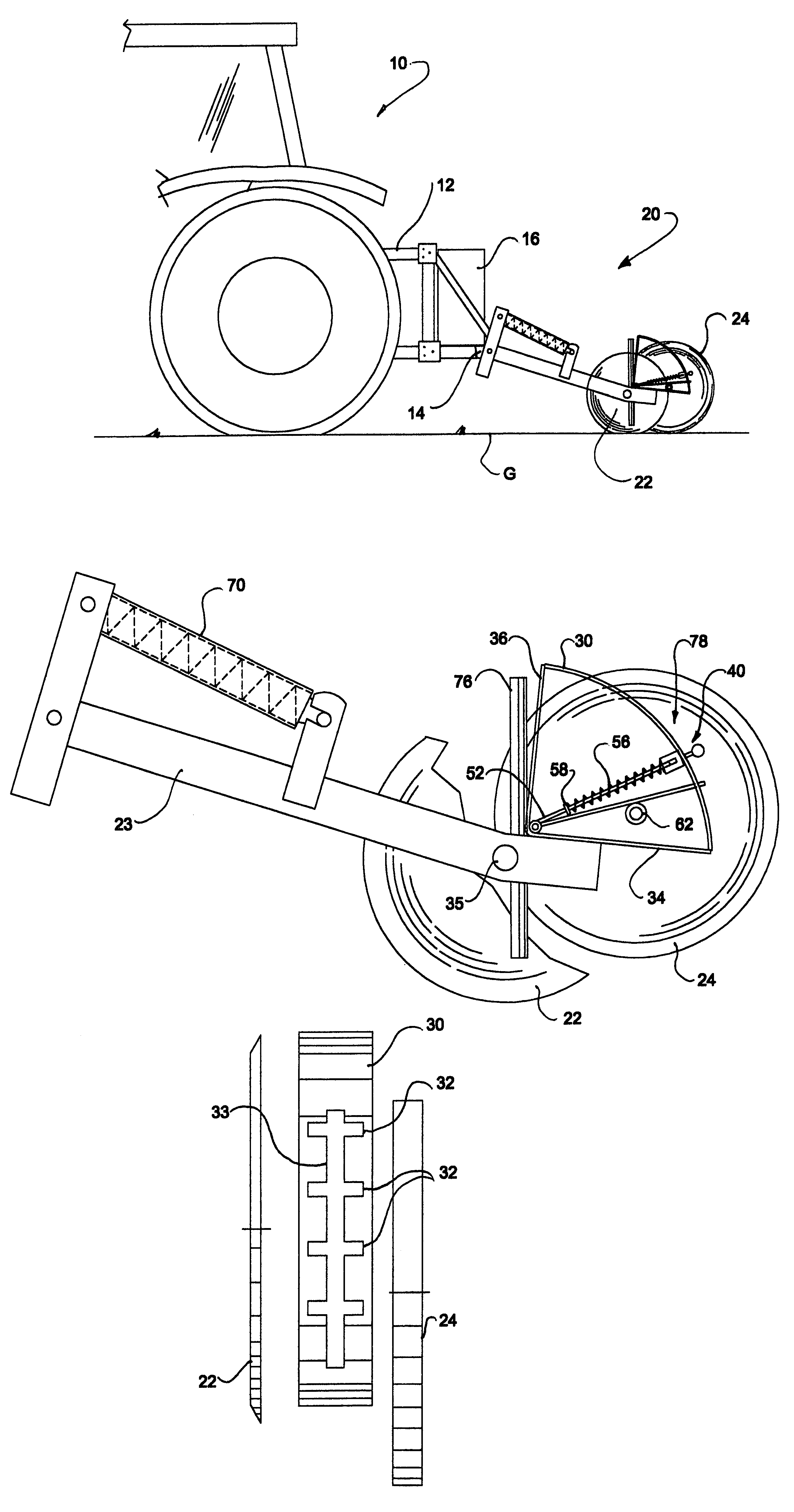
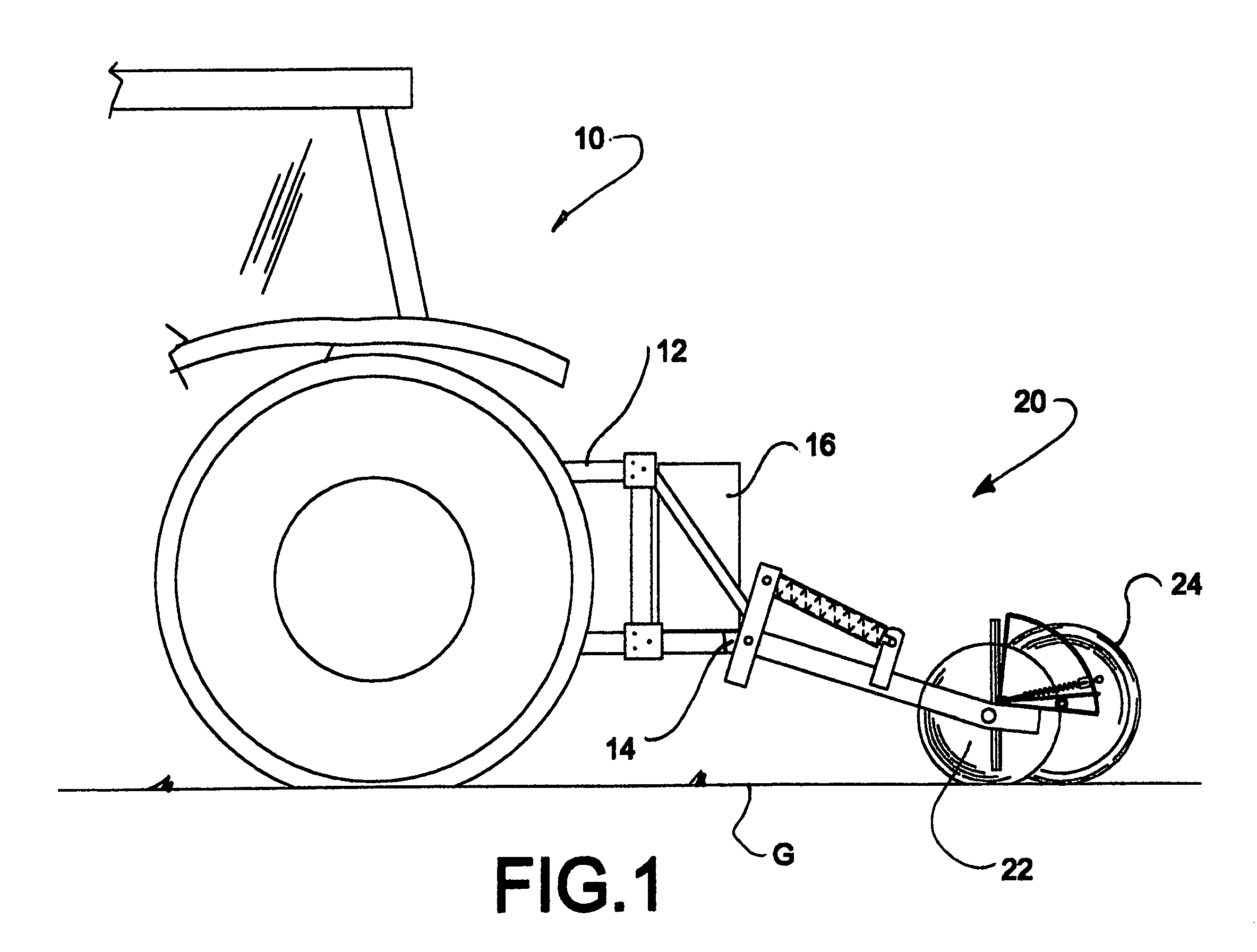
[0026]Referring now to FIG. 1, the present invention will be described in the context of an exemplary agricultural tractor 10 including ...


PUM


Abstract

A depth control mechanism for an agricultural seed planter is made up of an index plate, a T-handle, a spring, and a gauge wheel arm. The T-handle is moved into different positions which are indicated in the index plate. The spring and the gauge wheel arm allow for selective manual movement and locking of the depth adjustment.

Description

BACKGROUND OF THE INVENTION[0001]The present invention relates generally to agricultural planting equipment, and more specifically to depth gauging systems on disk openers and the like.[0002]Furrow depth or the planting of seeds in a furrow (which is the vertical distance therefrom to the top of the uniform soil covering of the seeds) is critical for successful crop production. Most planters, therefore, require a structure that will provide accurate furrow depth control. Most commonly dual disk openers are used to create the furrow for the seed deposited therein via a seed tube, with a gauge wheel positioned adjacent but outward to each disk with the wheel axis rearward of the disk axis and generally in line where the disk exits the soil. Various structures may be utilized to close the furrow. The gauge wheels are rotatably mounted on arms which are pivotally mounted on the planter frame. By moving the arms in one direction the gauge wheel position relative to the frame are changed ...

Claims


Application Information

Patent Timeline
IPC IPC(8): A01C5/00
CPCA01B63/166A01C7/203
Inventor GUST, JACOB N.
Owner BLUE LEAF I P
Why Eureka
Try Eureka