

Amphibious marine vehicle
- Summary
- Abstract
- Description
- Claims
- Application Information
AI Technical Summary
Problems solved by technology
Method used
Image

Examples
Embodiment Construction
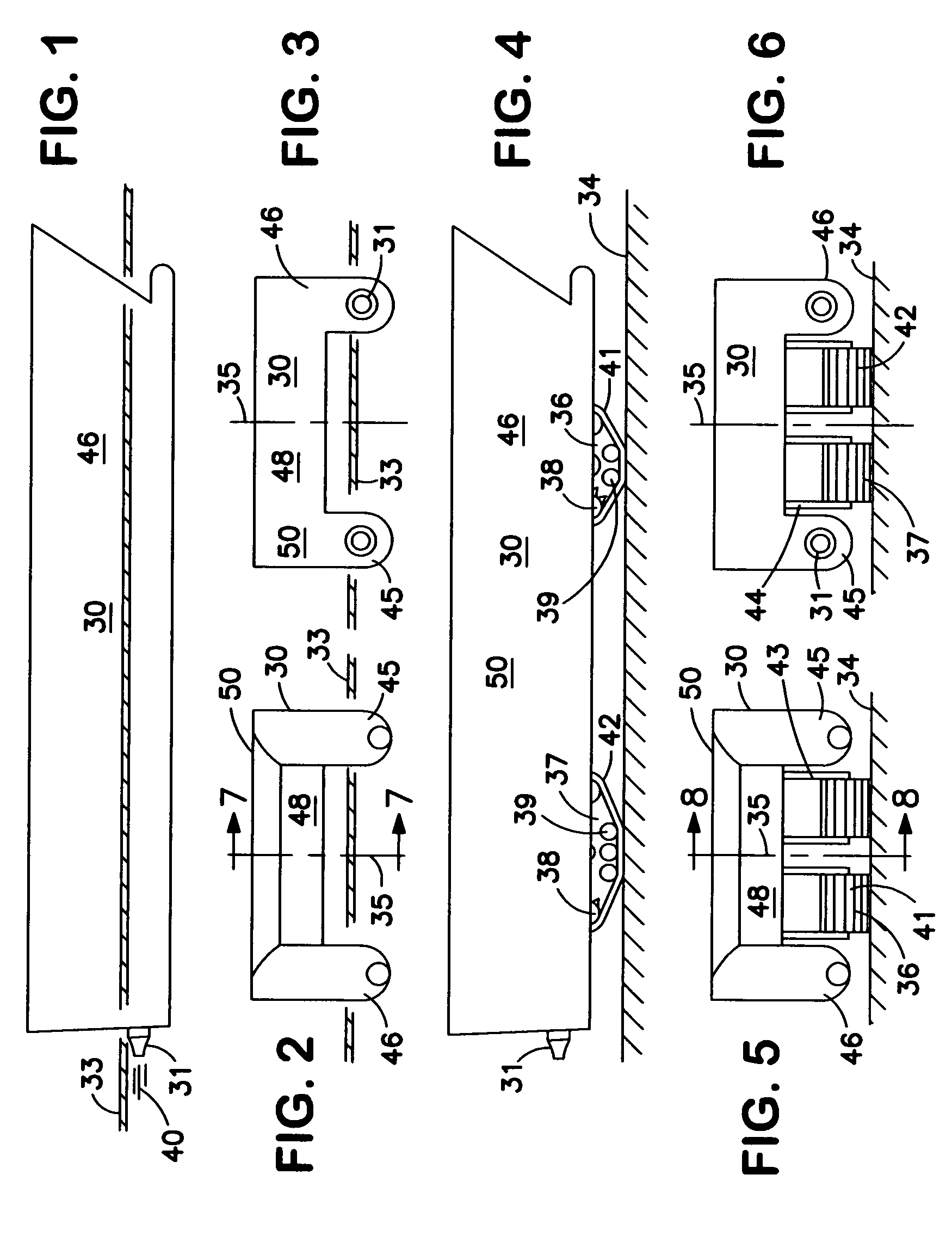
[0053]FIG. 1 presents a profile view of the instant invention amphibious marine vehicle 30 when it is operation water borne at high speed on a calm sea surface. The sea surface waterline 33, a water propulsor 31, water propulsor discharge flow 40, and starboard sidehull 46 of this hull variation that is a basic catamaran 50 as shown here.
[0054]FIG. 2 is a bow view of the instant invention vehicle 30 from FIG. 1. Additional items shown are port sidehull 45, multiple hull connecting structure 48, and vertical centerline plane 35.
[0055]FIG. 3 presents a stern view of the instant invention vehicle 30 of FIG. 1.
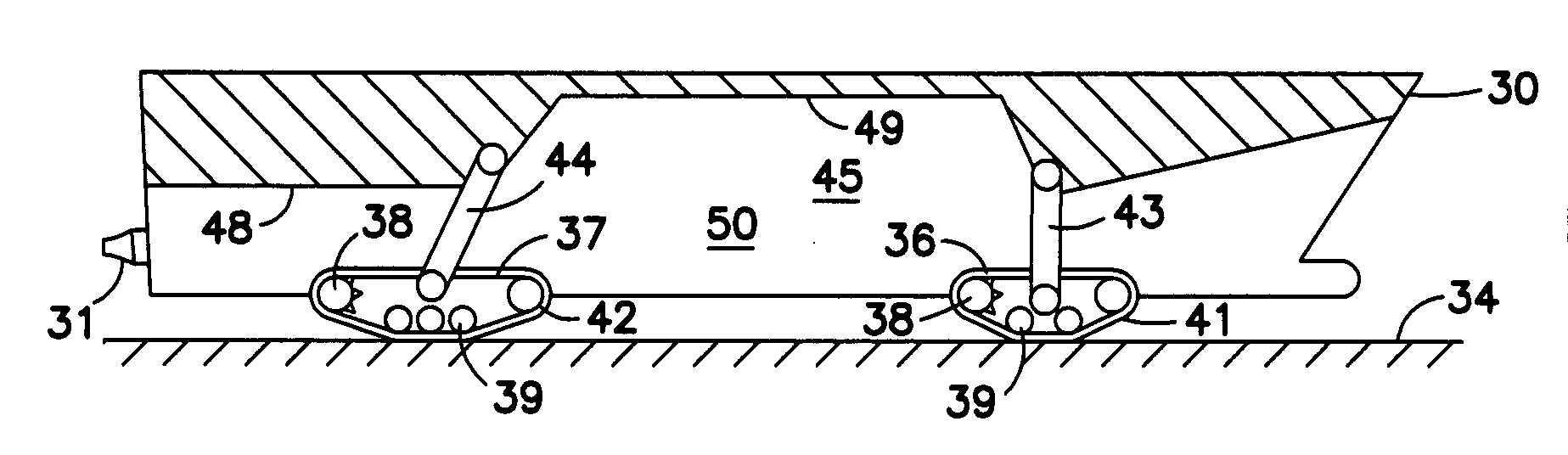
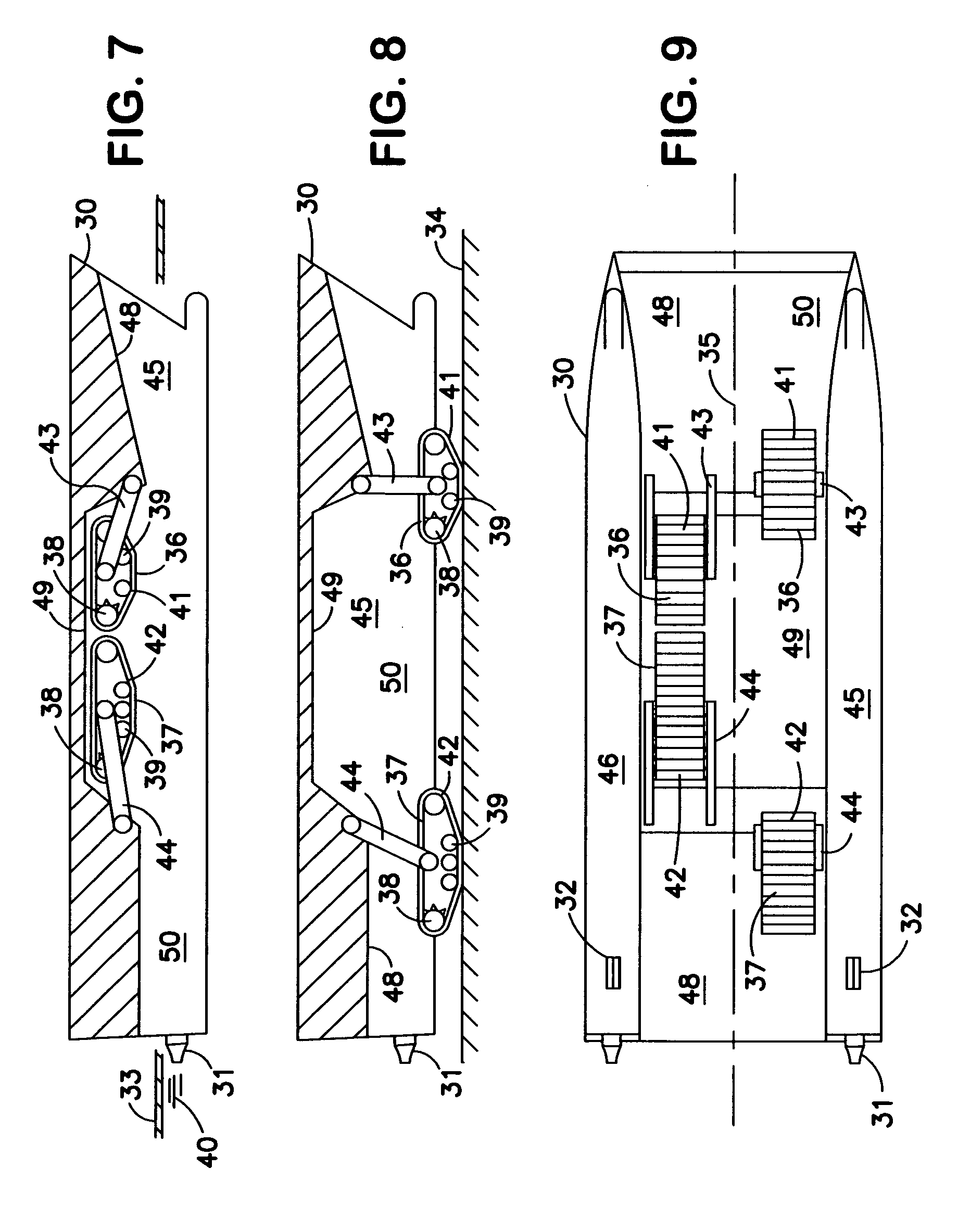
[0056]FIG. 4 is a profile view of the catamaran hull configuration version of the instant invention amphibious marine vehicle 30 when operating in its land borne mode. This shows its land drives or land transport means 36, 37 down and in land contact for over land transit. Components of the land drive shown, in this preferred embodiment, include: drive gears 38, forward track 41, ...
PUM
 Abstract
Description
Claims
Application Information