Conductor rail

a technology of conductor rails and rails, which is applied in the direction of power rails, power supply lines, vehicle components, etc., can solve the problems of shortening the life of contact shoes which slide upon weldments, difficult assembly of prior art facing layers such as described in u.s. pat. no. 5,279,397, etc., and achieves economic manufacture, refined appearance, and long service life

Active Publication Date: 2006-01-10
CONDUCTIX
View PDF4 Cites 32 Cited by
  • Summary
  • Abstract
  • Description
  • Claims
  • Application Information

AI Technical Summary

Benefits of technology

[0009]It is therefore a principal object of the invention to provide a conductor rail which is easily assembled.
[0012]Still another object of the invention is to provide a conductor rail which will perform satisfactorily for a long period of time.
[0013]Yet another object of the invention is to provide a conductor rail which is economical of manufacture, durable in use and refined in appearance.

Problems solved by technology

It is believed that the prior art facing layers such as described in U.S. Pat. No. 5,279,397 may be difficult to assemble.
It is also believed that the requirement of the weldment which attaches the two J-shaped members to the head portion of the main body in U.S. Pat. No. 5,047,597 shortens the life of the contact shoe which will slide upon the weldment even though the weldment has been ground or smoothed.

Method used


Image

  • Conductor rail
  • Conductor rail
  • Conductor rail

Examples


Embodiment Construction

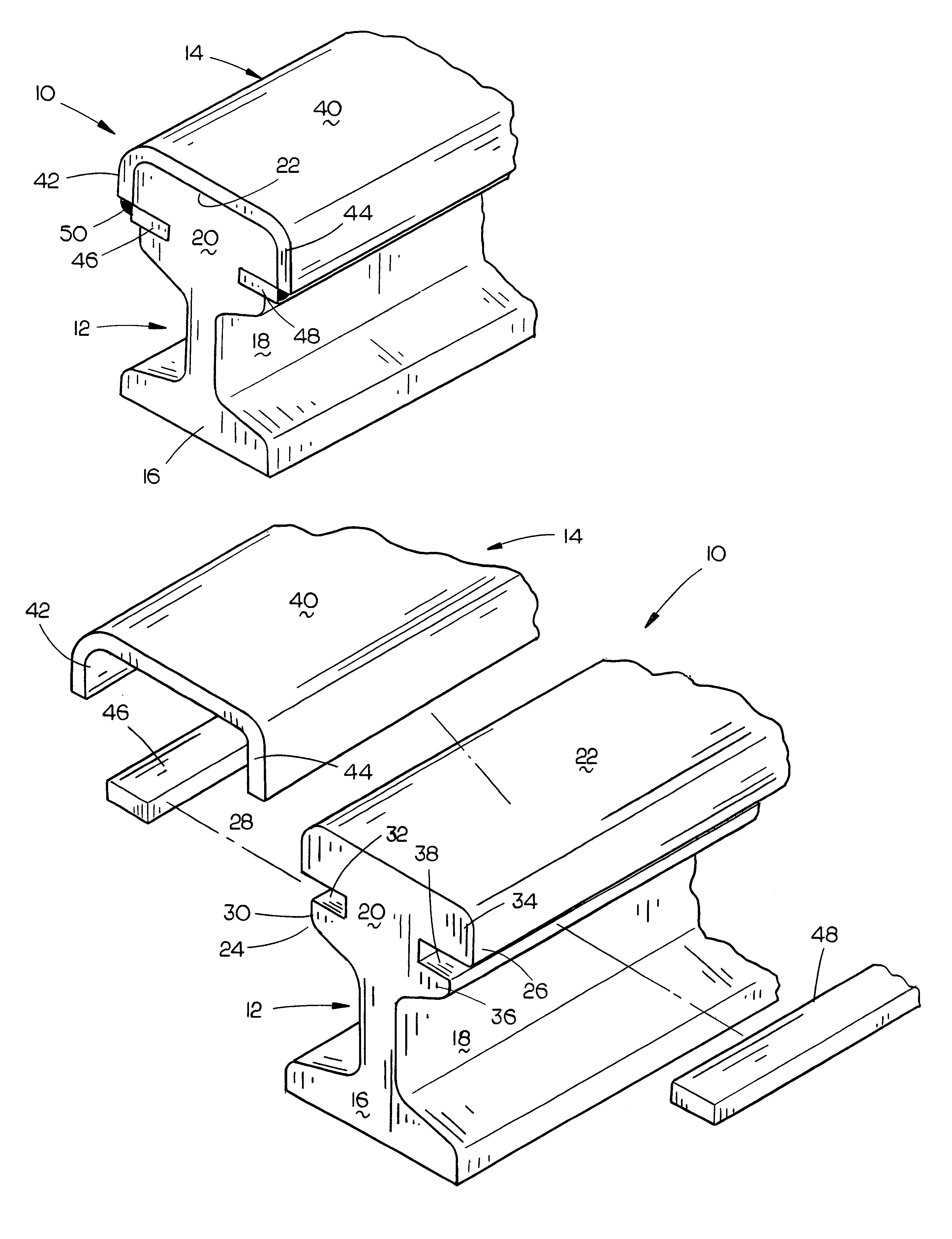
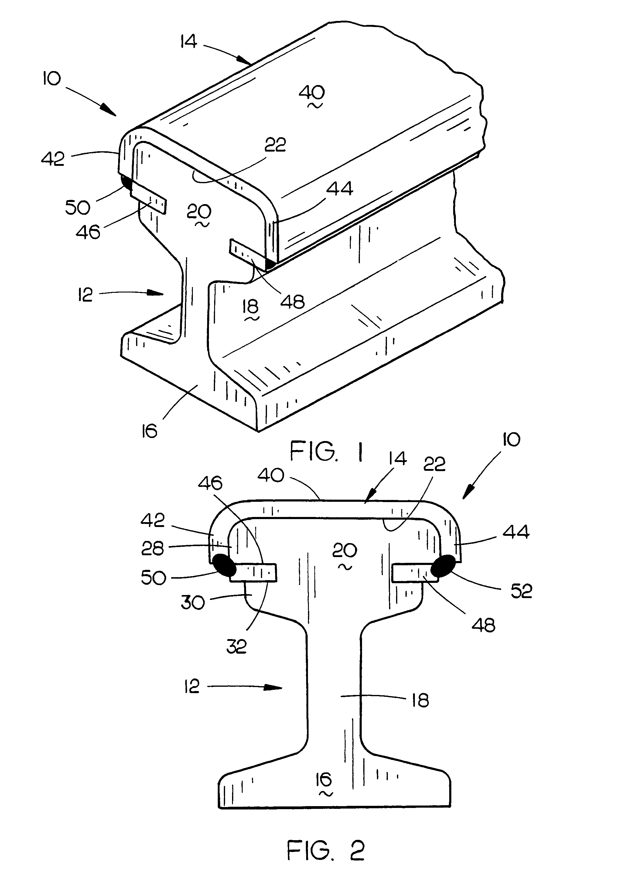
[0018]The conductor rail of this invention is referred to generally by the reference numeral 10 which includes a main body 12 and a facing cap 14 attached thereto. Main body 12 is preferably comprised of an aluminum alloy material such as 6101 or 6063 while cap 14 is preferably comprised of a 300 series stainless steel such as 301 with a 2B finish. Both the 6101 and 6063 alloy aluminum materials are relatively low in electrical resistance.

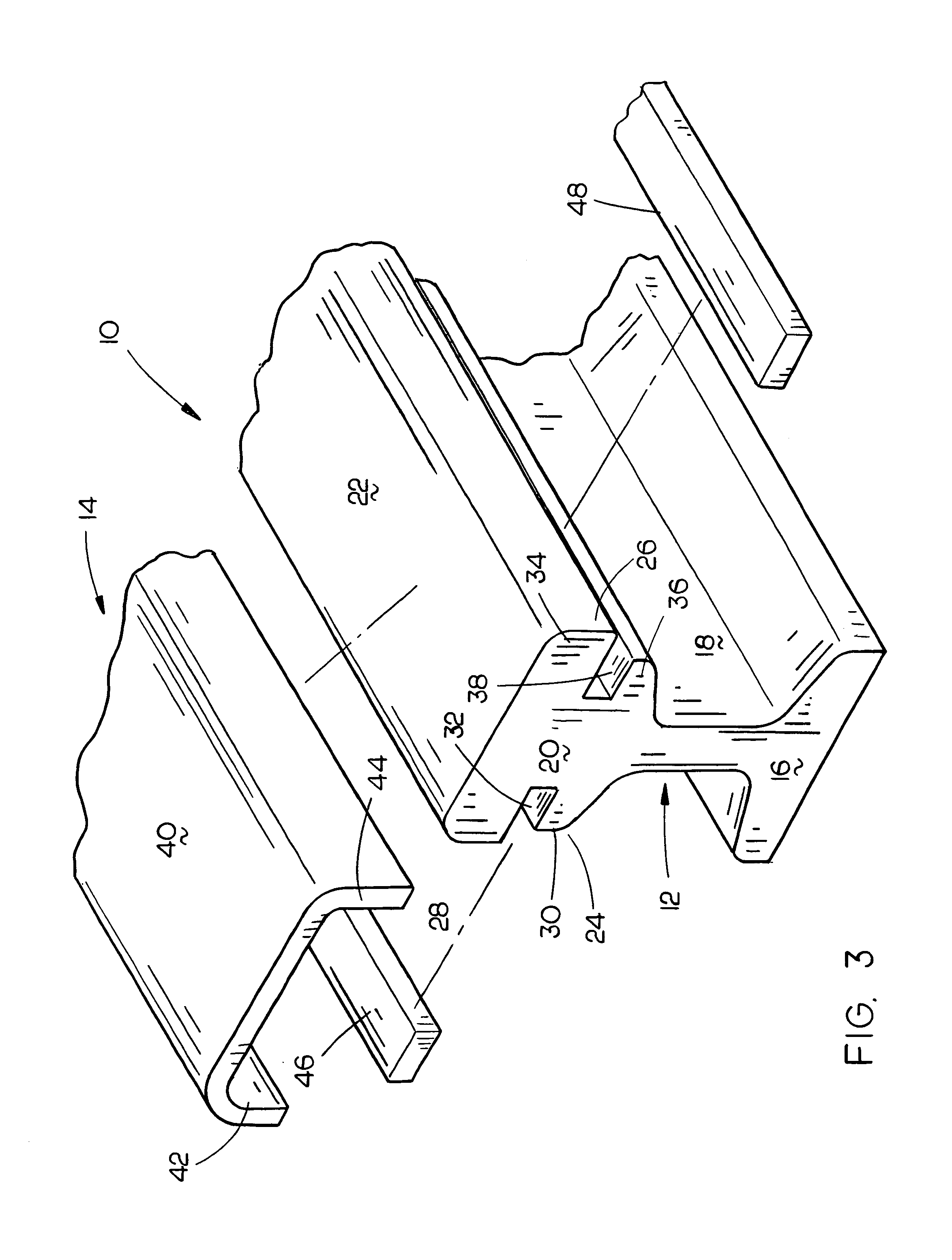
[0019]Main body 12 includes a base portion 16, vertical stem portion 18 and head portion 20. Head portion 20 includes a top surface 22 and opposite side edges 24 and 26. Side edge 24 of head portion 20 includes an upper side portion 28 and a lower side portion 30. As seen, lower side portion 30 is spaced inwardly of side edge portion 28. A channel 32 extends inwardly into head portion 20 at side portion 24 at the juncture of side edge portions 28 and 30, as seen in FIG. 3. Similarly, side portion 26 of head portion 20 includes an upper side edge po...


PUM


Abstract

A conductor rail comprising a main body having a facing cap mounted thereon. The main body is comprised of aluminum while the facing cap is comprised of a stainless steel material. The main body of the conductor rail has a head portion which has channels extending into the opposite sides thereof. The facing cap comprises a top portion which is positioned upon the upper part of the head portion and which has side portions welded to plate members positioned in the channels.

Description

BACKGROUND OF THE INVENTION[0001]1. Field of the Invention[0002]This invention relates to a conductor rail, such as is used in electric railway systems, overhead conveyors, etc., and which has a main body of aluminum and a stainless steel facing cap.[0003]2. Description of the Related Art[0004]Many types of conductor rails have been previously provided which are used in electric railway systems and which are also used on overhead conveyors, etc. The conductor rails of the prior art include a main body of aluminum and a facing layer or facing cap comprised of a stainless steel material to provide a wear-resisting engagement surface for a contact shoe which slides against the top surface of the facing layer or cap rather than the top surface of the main body.[0005]The prior art facing layers or caps include many different designs and many different methods of attaching the facing layers or caps to the main body. In some cases, the facing layers or caps are snapped into place on the he...

Claims


Application Information

Patent Timeline
Patent Type & Authority Patents(United States)
IPC IPC(8): B60M1/00
CPCB60M1/302
Inventor KRAUDY, KYLE D.
Owner CONDUCTIX
Why Eureka
Try Eureka