Deployable solar array assembly

a solar array and solar cell technology, applied in the field of solar arrays for spacecraft, can solve the problems of reducing the stiffness of the solar cell array, and affecting the general utility of most previously available solar cell arrays

Active Publication Date: 2006-01-10
THE BOEING CO
View PDF8 Cites 59 Cited by
  • Summary
  • Abstract
  • Description
  • Claims
  • Application Information

AI Technical Summary

Benefits of technology

[0010]In accordance with a further exemplary embodiment of the present invention, a solar cell array system for deployment from a spacecraft is provided. The solar cell array system comprises a solar cell panel assembly that has a flexible solar panel having a first longitudinal axis. A rotating member is coupled to a first end of the flexible solar panel. When the solar cell panel assembly is in a stored mode, the flexible solar panel is wound about the rotating member. When the solar cell panel is being deployed, the rotating member is configured to rotate about a second longitudinal axis so that the flexible solar panel may be unwound from the rotating member. A first longitudinal stabilizing means for stabilizing the flexible solar panel along the first longitudinal axis is coupled to a first end of the rotating member and a second longitudinal stabilizing means for stabilizing the flexible solar panel along the first longitudinal axis is coupled to a second end of the rotating member. The solar cell panel assembly further comprises a first tether means for applying a compressive force to an end of the first longitudinal stabilizing means and a second tether means for applying a compressive force to an end of the second longitudinal stabilizing means. The solar cell array system further comprises a deployment means for deploying the solar cell panel assembly from the spacecraft.

Problems solved by technology

The general utility of most previously available solar cell arrays has been impaired by the tendency of the solar cell array to vibrate at a low frequency in orbit.
However, as the size of the solar cell panels and the solar cell array increase, the stiffness of the solar cell array decreases and, as a result, the vibration frequency decreases.
If the flopping, fluttering and waving of the solar cell array in space is too excessive, the ability of the spacecraft attitude control system to orient the spacecraft is impaired and the spacecraft cannot perform its intended function in orbit.
In addition, the efficiency of the solar cell array is reduced and damage to the solar cell array may result.
Previous attempts to achieve adequate stiffness of the solar cell arrays have proven unsatisfactory.
On the one hand, power production is compromised if low stiffness is avoided by reducing the size of the solar cell panels and the solar cell array.
On the other hand, the use of various stiffeners and rigid structures to stabilize a solar cell array increases the bulk of the solar cell array, making it heavier and more difficult to stow for launch.
Moreover, as the complexity of the deployment structures of the large solar cell array increases, the reliability of the structure decreases.

Method used


Image

  • Deployable solar array assembly
  • Deployable solar array assembly
  • Deployable solar array assembly

Examples


Embodiment Construction

[0024]The following detailed description of the invention is merely exemplary in nature and is not intended to limit the invention or the application and uses of the invention. Furthermore, there is no intention to be bound by any theory presented in the preceding background of the invention or the following detailed description of the invention.

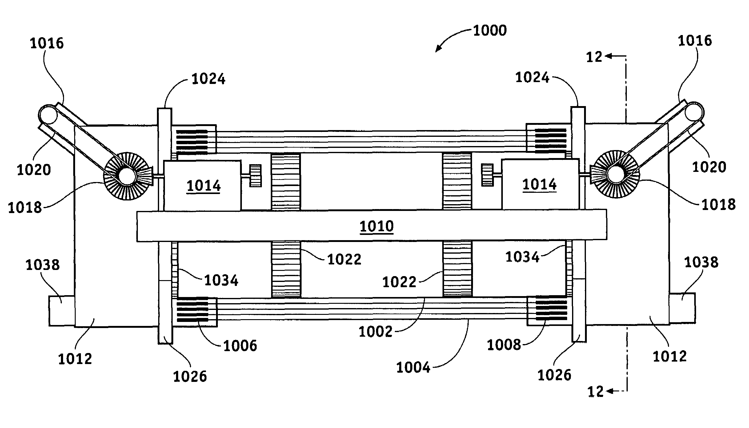
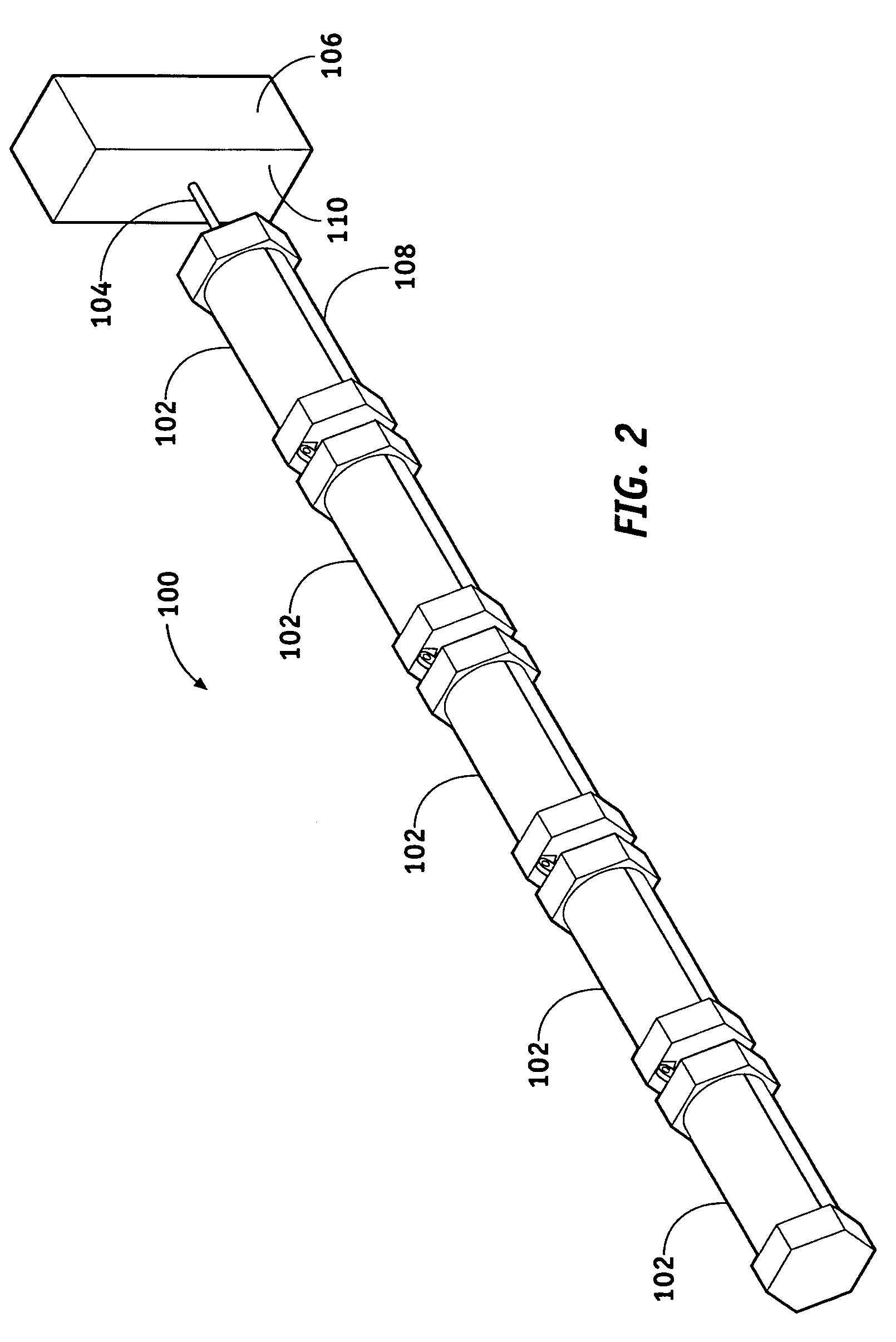
[0025]The various embodiments of the present invention relate to a solar cell array system that is configured to be compact when stored on a spacecraft and deployable at a desired time after launching of the spacecraft. The solar cell array system may utilize at least one solar cell panel assembly comprising at least one flexible solar cell panel. Upon deployment, the solar cell array system orients the solar cell panel assemblies, if more than one, so that the flexible solar cell panels may be released from the solar cell panel assemblies, forming a solar array. In one embodiment of the invention, upon deployment, the solar cell panel assem...


PUM


Abstract

Solar array assemblies and systems and methods for deploying solar cell arrays from a spacecraft. A solar cell panel assembly comprises a first flexible solar panel and a rotational member. A first extension assembly is disposed proximate to a first end of the rotational member and a second extension assembly is disposed proximate to a second end of the rotational member. The solar cell panel assembly further comprises a first support member and a second support member. The first end of the first support member is coupled to the first end of the rotational member and the first end of the second support member is coupled to the second end of the rotational member. The second ends of the support members are coupled to the first flexible solar panel. A tether assembly couples the extension assemblies to the support members.

Description

STATEMENT REGARDING FEDERALLY SPONSORED RESEARCH OR DEVELOPMENT[0001]The U.S. Government has a license in this invention as provided by the terms of Agreement No. F29601-01-2-0042 awarded by the U.S. Air Force.FIELD OF THE INVENTION[0002]The present invention generally relates to solar arrays for spacecraft, and more particularly relates to flexible solar arrays deployable from a spacecraft.BACKGROUND OF THE INVENTION[0003]Solar cell arrays are widely used in space as the primary power source for certain spacecraft, such as satellites, due to their reliability and light weight. A typical spacecraft 10 orbiting the earth 12 is illustrated in FIG. 1. Satellite 10 comprises a spacecraft platform 14 from which extends two solar cell wings 16, which form the solar cell array of the satellite. Each solar cell wing 16 comprises a series of panels 18 attached to each other by hinges and attached to the spacecraft by a yoke 20.[0004]Typically, solar cell arrays are stored in a compact manner...

Claims


Application Information

Patent Timeline
Patent Type & Authority Patents(United States)
IPC IPC(8): B64G1/44B64G1/22B64G1/64
CPCB64G1/222B64G1/443Y10S136/292
Inventor STRIBLING, RAY A.SCHWARTZ, JOEL A.
Owner THE BOEING CO
Why Eureka
Try Eureka