Backrest assembly for motorcycle

a backrest and motorcycle technology, applied in the field of backrest assemblies, can solve the problems of large-scale mounting operation to the body of the motorcycle, the arm cannot be adjusted at all as the backrest for the rear rider, and the inability to pivot behind, etc., to achieve the effect of reliably secure, easy adjustment of the angle of the backrest, and no negative influence on the appearance of the motorcycl

Active Publication Date: 2006-01-10
HONDA MOTOR CO LTD
View PDF17 Cites 41 Cited by
  • Summary
  • Abstract
  • Description
  • Claims
  • Application Information

AI Technical Summary

Benefits of technology

[0006]In view of the above problems, it is an object of the present invention to provide a backrest assembly that can reliably adjust the angle of a backrest and can be made compact at lower cost and can have a pleasing appearance on a motorcycle.
[0008]According to the present invention, each of the metal arms is attached to a corresponding seat stay by a connecting shaft so that the backrest is pivotable. Moreover, since the lower ends of each metal arm extending below the connecting shafts are retained at a desired angular position by the retaining units, the angle of the backrest can be secured reliably. Since the retaining units are provided at the lower ends of the metal arms, the backrest assembly can be made compact, and the retaining units can be hidden inside the seat stays. Therefore, the retaining units can be provided without negatively affecting the appearance of the motorcycle. Furthermore, since the retaining units are biased in the retaining direction by the biasing members, retention of the lower ends of the metal arms by the retaining units is prevented from being released accidentally. In addition, the angle of the backrest can be easily adjusted merely by releasing the retention by the retaining units against the biasing forces of the biasing members.
[0009]Preferably, each retaining unit includes a base member having a plurality of recesses, and the base member is provided on one of the corresponding metal arm and the corresponding seat stay, and a claw provided in the other of the corresponding metal arm and the corresponding seat stay so as to be selectively retained in the recesses, and one of the claw and the base member is separable from the other and is biased in the retaining direction by the biasing member. In this case, the angle of the backrest can be easily adjusted merely by disengaging the claw from a recess against the biasing force of the biasing member and retaining the claw in another recess corresponding to a desired angle. Since the claw can be reliably held in the recess by the biasing member, the backrest can be prevented from undesirable pivotal motion. Moreover, since the claw and the base member that define the retaining unit are provided, respectively, on the metal arm and on the seat stay, it is unnecessary to further process the body of the motorcycle, and this reduces the cost.

Problems solved by technology

In the above backrest assembly, the arm can pivot forward relative to the frame in order to adjust the angle thereof, but the arm cannot pivot behind the frame, because the frame standing behind the seat is not pivotable.
For this reason, the arm can be adjusted as the backrest for the front rider on a tandem seat, but the arm cannot be adjusted at all as the backrest for the rear rider.
Moreover, since the frame must stand behind the seat in order to mount the lock plates thereon, a large-scale mounting operation to the body of the motorcycle is required.
This increases the cost and deteriorates the appearance.

Method used


Image

  • Backrest assembly for motorcycle
  • Backrest assembly for motorcycle
  • Backrest assembly for motorcycle

Examples


Embodiment Construction

[0023]An embodiment of the present invention will be described below with reference to the attached drawings.

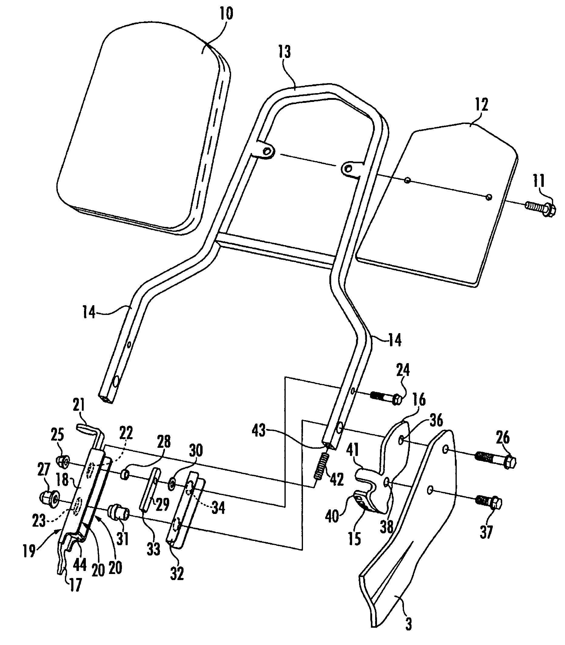
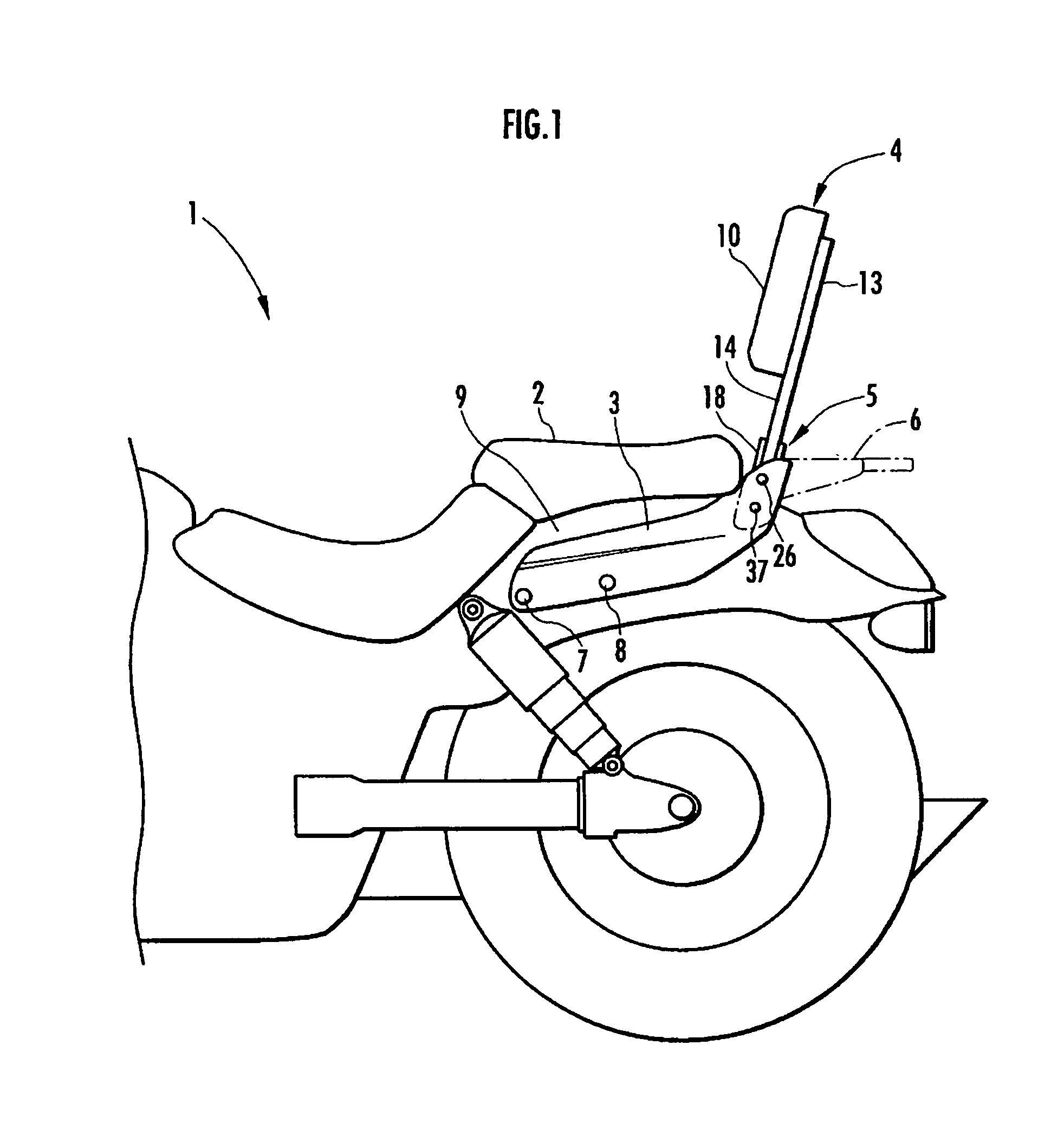
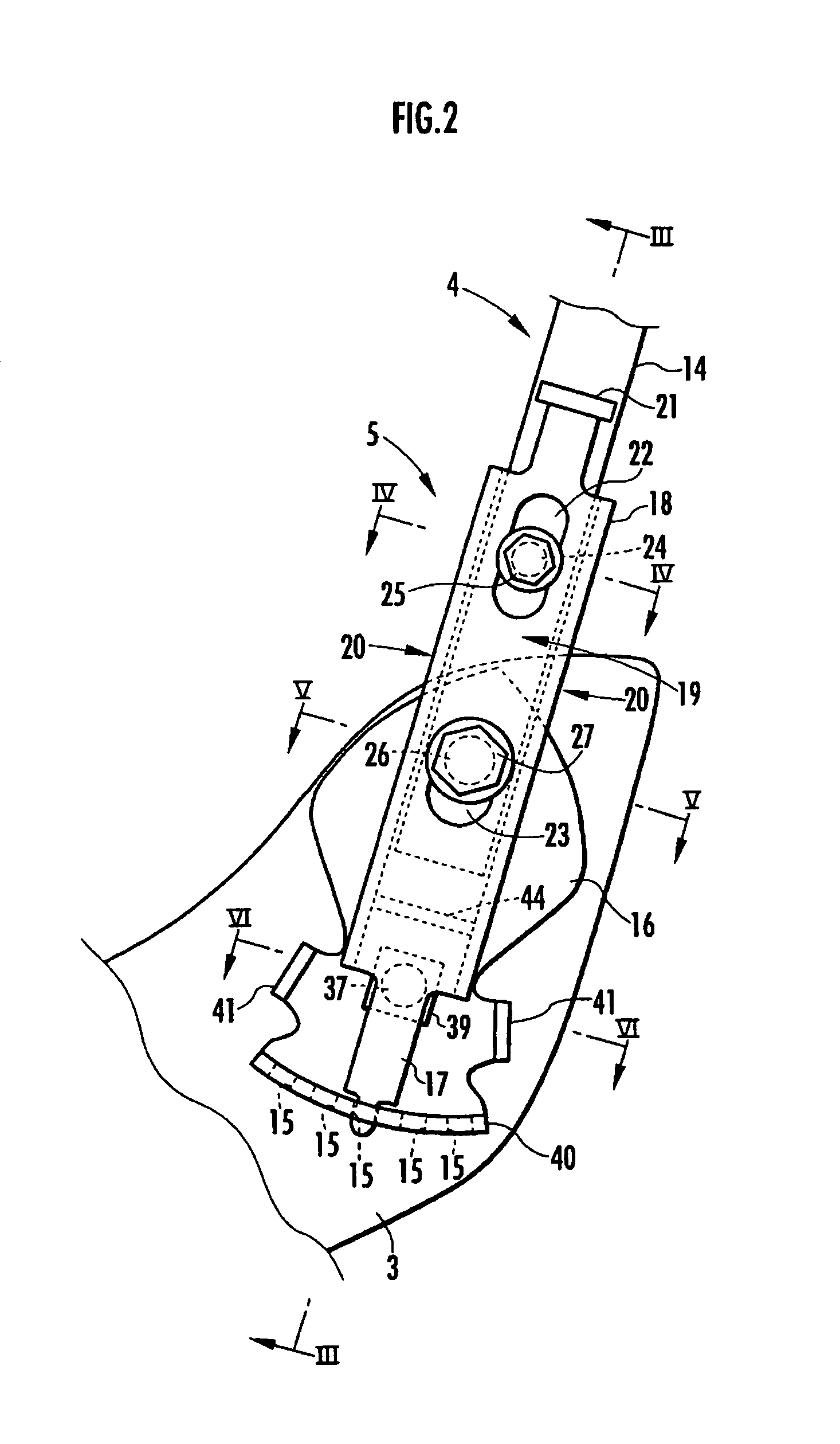
[0024]FIG. 1 shows the rear half of a motorcycle 1. In the motorcycle 1, a pair of seat stays 3 are provided on both sides of a seat 2 (a rear part of a tandem seat in this embodiment). A backrest 4 and a pair of angle-adjusting units 5 for adjusting the angle of the backrest 4 to a desired angle are provided on the rear sides of the seat stays 3 to define the backrest assembly of the present invention.

[0025]A rear carrier 6 is connected to the rear sides of the seat stays 3, as necessary. The seat stays 3 are each made of a chromium-plated iron plate, and are symmetrically arranged and fixed to a seat frame 9 by a plurality of bolts 7 and 8.

[0026]As shown in FIGS. 1 and 7, the backrest 4 includes a back cushion 10, a back support member or a cushion support 13 to which the back cushion 10 is attached together with a cover 12 by bolts 11, and a pair of arms 14 (metal arms) ex...


PUM


Abstract

A backrest of a motorcycle is provided with a pair of angle-adjusting units. In each angle-adjusting unit, a metal arm of the backrest is pivotally connected, by a connecting shaft, to an inner side of each of a seat stay mounted along a side of a seat. A retaining unit selectively and detachably retains a lower end of the metal arm at a plurality of retaining positions. The retaining unit is biased by a biasing member in a retaining direction.

Description

BACKGROUND OF THE INVENTION[0001]1. Field of the Invention[0002]The present invention relates to a backrest assembly that allows the angle of a backrest provided behind a seat of a motorcycle to be adjusted to a desired angle.[0003]2. Description of the Related Art[0004]Japanese Examined Utility Model Registration Application Publication No. 2-38872 (FIGS. 1 to 3) discloses a backrest assembly that includes a frame standing behind a seat, and an arm having an upper end for supporting a back cushion and a lower end pivotally attached to the frame. The angle of the backrest can be adjusted by engaging a connecting rod provided above the pivot position of the arm with lock plates provided in the frame.[0005]In the above backrest assembly, the arm can pivot forward relative to the frame in order to adjust the angle thereof, but the arm cannot pivot behind the frame, because the frame standing behind the seat is not pivotable. For this reason, the arm can be adjusted as the backrest for ...

Claims


Application Information

Patent Timeline
Patent Type & Authority Patents(United States)
IPC IPC(8): B60N2/02A47C1/08B62J1/28A47C15/00A47D1/10B62J1/12
CPCB62J1/28B62J1/12
Inventor OOMORI, HIROYASU
Owner HONDA MOTOR CO LTD
Why Eureka
Try Eureka