Head amplifier with a heat controller

Active Publication Date: 2008-04-10
TDK CORPARATION
View PDF7 Cites 17 Cited by
  • Summary
  • Abstract
  • Description
  • Claims
  • Application Information

AI Technical Summary

Benefits of technology

[0014]Therefore, an object of the present invention is to achieve a timely and proper flying height adjustment with a HDC, which is de

Problems solved by technology

However, the conventional heat generation control method described above has a problem that the new function must be added to the HDC.
That is, there has been an inconvenience that, in the present state of the art, different HDCs need to be prov

Method used


Image

  • Head amplifier with a heat controller
  • Head amplifier with a heat controller
  • Head amplifier with a heat controller

Examples


first embodiment

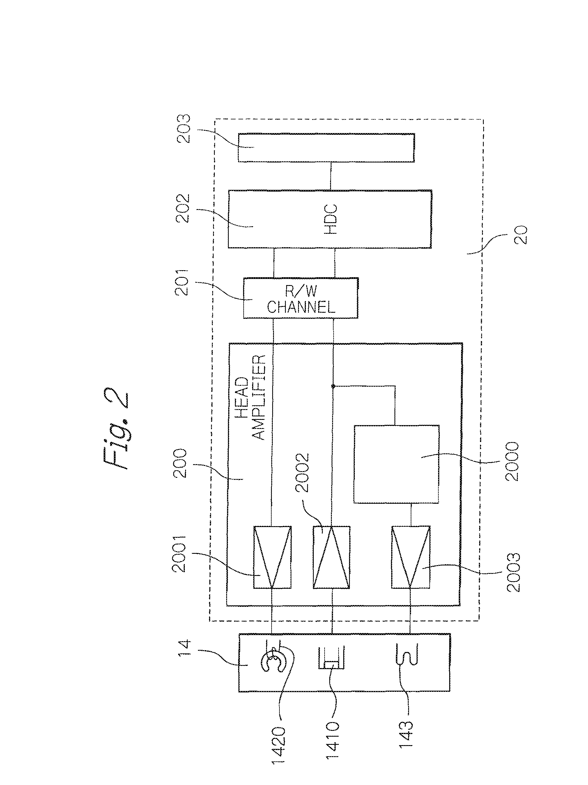
[0052]FIG. 2 is a circuit block diagram showing a head amplifier according to the present invention.

[0053]Referring to FIG. 2, the head amplifier 200 is one component of a recording / reproducing and flying height control circuit 20, which also includes a read / write (R / W) channel 201, an HDC 202, and an interface 203. The R / W channel 201 code-modulates a data signal received from the HDC 202 into a write signal and outputs the write signal to the head amplifier 200, and, on the other hand, code-demodulates a read signal output from the head amplifier 200 into a data signal and outputs the data signal to the HDC 202.

[0054]The HDC 202 is conventional one designed for use in magnetic disk apparatuses that includes a magnetic head without a heating element for flying height adjustment. That is, the HDC 202 adds an error correction code to a data signal it received from an external host system through the interface 203 and outputs the data signal to the R / W channel 201, and, on the other h...

second embodiment

[0068]FIG. 4 is a circuit block diagram showing a head amplifier according to the present invention.

[0069]As shown in FIG. 4, a touchdown detecting unit 40, which detects a contact of a magnetic head with a magnetic disk, is provided in the second embodiment. A heat controller 2000′ and an HDC 202′ receive a touchdown detection signal from the touchdown detecting unit 40. The rest of the configuration of the second embodiment is the same as the first embodiment and therefore the description of which will be omitted.

[0070]The term “touchdown” herein refers to an action of intentionally bringing a magnetic head into contact with the surface of a magnetic disk in order to check and adjust the flying height. Touchdown may be made during startup of the apparatus, or when a signal from an impact sensor provided in the apparatus is received, or at predetermined time intervals. Touchdown may be performed, for example, as follows. A reset signal may be sent to the heating element driver 2003...

third embodiment

[0076]FIG. 5 is a circuit block diagram showing a head amplifier according to the present invention.

[0077]A heat controller 2000″ in the third embodiment shown in FIG. 5 has a configuration as shown in FIG. 3, and a state variable managing unit 33″ receives a write signal output from an HDC 202′ and performs processing according to the write signal. The rest of the configuration of the head amplifier according to the third embodiment is the same as that in the second embodiment and therefore the description of which will be omitted.

[0078]In FIG. 5, the state variable managing unit 33″ monitors a write signal output from the HDC 202′ to a write amplifier 2001. When an output comparing unit 30″ requests a data value in a state variable table 320″, the state variable managing unit 33″ retrieves the data value from the state variable table 320″ that corresponds to the write signal it received. For example, the state variable table 320″ contains the relationship between the value of the ...


PUM


Abstract

Timely and proper flying height adjustment is achieved using a controller, which is designed for a magnetic recording and reproducing apparatus that does not use a magnetic head having a heating element for flying height adjustment without any modification. A head amplifier includes a write amplifier for applying a write current to a write head element, a read amplifier for amplifying a read voltage output from a read head element and outputting a read signal, a heating element driver for applying a heat generating current to at least one heating element for adjusting a flying height, and a heat controller for controlling the heating element driver.

Description

PRIORITY CLAIM[0001]This application claims priority from Japanese patent application No. 2006-272846 filed on Oct. 4, 2006, which is incorporated herein by reference.BACKGROUND OF THE INVENTION[0002]1. Field of the Invention[0003]The present invention relates to a head amplifier for a head that magnetically writes and reads data signals, a recording and reproducing control circuit including the head amplifier, and a magnetic recording and reproducing apparatus including the recording and reproducing control circuit, and, in particular, to a head amplifier for a head including a heating element for adjusting the flying height of the head with respect to a magnetic recording medium.[0004]2. Description of the Related Art[0005]Thin-film magnetic heads included in magnetic disk apparatuses, which are typical magnetic recording and reproducing apparatuses, hydrodynamically fly above rotating magnetic disks with predetermined gaps (flying heights), while in writing and reading signals. A...

Claims


Application Information

Patent Timeline
IPC IPC(8): G11B5/09
CPCG11B5/3136G11B5/6064G11B5/6005G11B5/3133G11B5/607
Inventor OHTA, NAOKIKUWASHIMA, TETSUYA
Owner TDK CORPARATION
Why Eureka
Try Eureka