Offset adjustment device, semiconductor device, display device, offset adjustment method, noise detection device, and noise detection method

Active Publication Date: 2008-10-09
SHENZHEN TOREY MICROELECTRONIC TECH CO LTD
View PDF7 Cites 17 Cited by
  • Summary
  • Abstract
  • Description
  • Claims
  • Application Information

AI Technical Summary

Benefits of technology

[0031]The storage section stores the binary logical signal indicative of the offset of the output voltage of the operational amplifier, the binary logical signal having (i) a first logical value in a case where the output voltage is positive with respect to the reference value, and (ii) a second logical value in a case where the output voltage is negative with respect to the reference value, and the offset of the output voltage is adjusted using the stored logical signal. Consequently, a large capacity or a frequent refreshment process is not required unlike a case where an

Problems solved by technology

In recent years, a load of the liquid crystal panel has been increasingly becoming large for a drive circuit, with an increase in the size of the liquid crystal panel.
Thus, the line-by-line variation in the drive voltages applied to the data lines causes a non-uniform display.
These methods, however, lead to an increase in the size of a chip and in production costs, when an offset adjustment circuit is formed into an LSI.
However, in either cas

Method used


Image

  • Offset adjustment device, semiconductor device, display device, offset adjustment method, noise detection device, and noise detection method
  • Offset adjustment device, semiconductor device, display device, offset adjustment method, noise detection device, and noise detection method
  • Offset adjustment device, semiconductor device, display device, offset adjustment method, noise detection device, and noise detection method

Examples


Embodiment Construction

[0097]The following describes an embodiment of the present invention with reference to FIGS. 1 to 15.

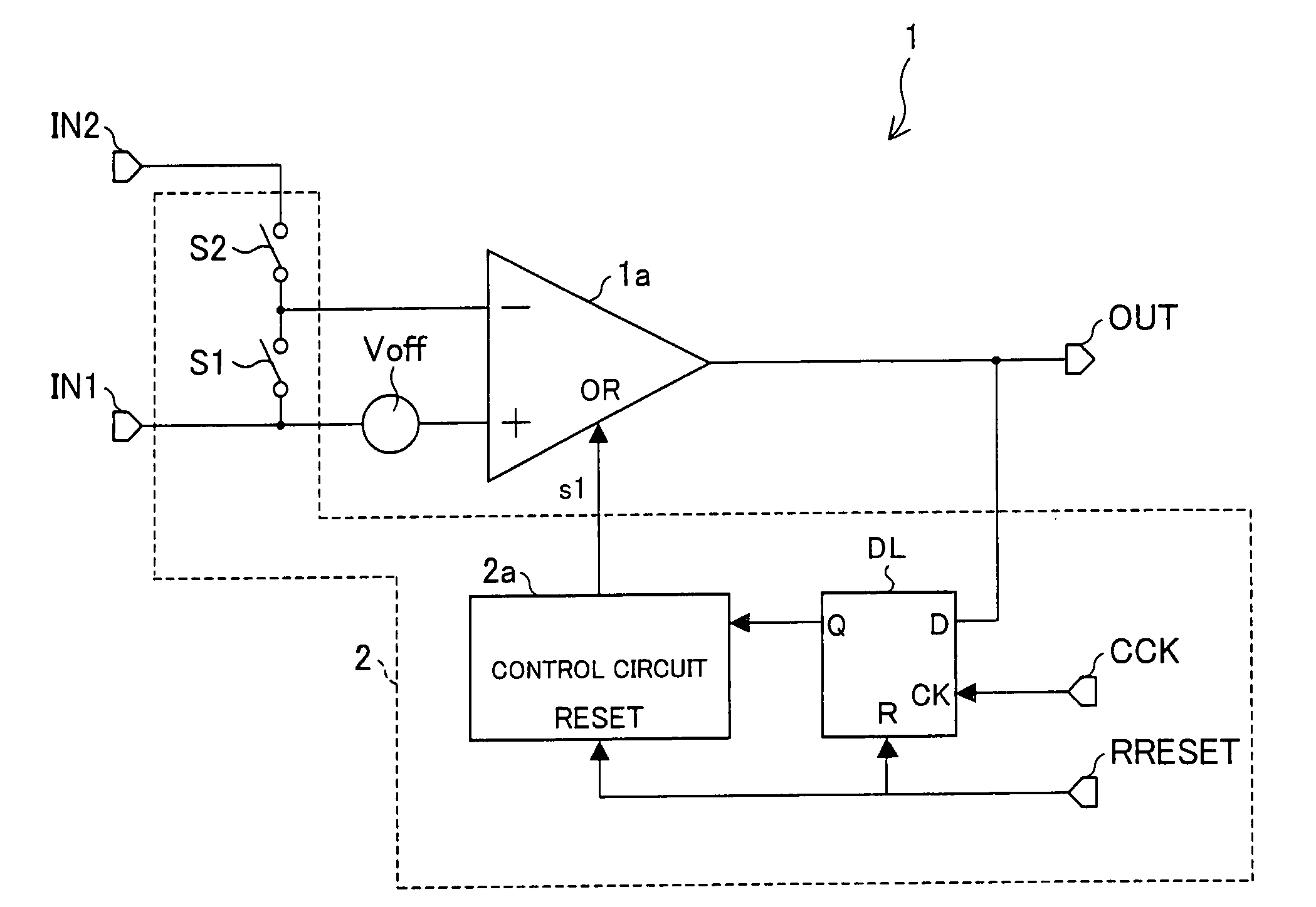
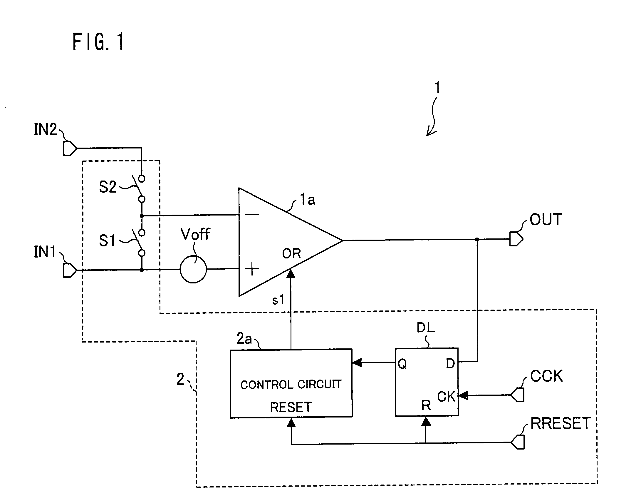
[0098]FIG. 1 is a circuit block diagram of an embodiment of the present invention, illustrating a configuration of an operational amplifier circuit (offset adjustment device) 1 including a first offset adjustment circuit.

[0099]An operational amplifier circuit 1 includes: an operational amplifier 1a; an offset adjustment circuit 2; a common phase input terminal IN1; a negative-phase input terminal IN2; and an output terminal OUT. Note that, an offset of an output voltage of the operational amplifier 1a is represented by a voltage source Voff which serves as a power source for indicating an input offset of a common phase input signal. This voltage source Voff is provided between a non-inverting input terminal of the operational amplifier 1a and the common phase input terminal IN1. Accordingly, a cause of an offset is removed from the operational amplifier 1a itself illustrated in the f...


PUM


Abstract

In one embodiment of the present invention, an operational amplifier circuit, a switching element is closed and a switching element is opened. A latch circuit DL latches an output voltage of an operational amplifier and supplies a Q output corresponding to the output voltage. A control circuit supplies an offset adjustment signal to an offset adjustment input terminal OR of the operational amplifier, thereby adjusting an offset of the output voltage. The latch circuit DL latches again the output voltage thus adjusted and minutely adjusts the offset adjustment signal so as to adjust the remaining offset. Weighting is carried out in accordance with how many times latching has been carried out, and the offset of the output voltage of the operational amplifier is quantized, thereby obtaining a binary logical signal and storing the signal in the control circuit. This realizes a small-scale offset adjustment device which is capable of absorbing offset variations and which does not require a frequent refreshment process.

Description

[0001]This non-provisional application claims priority under 35 U.S.C. § 119(a) on Patent Application No. 2006-213886 filed in Japan on Aug. 4, 2006, the entire contents of which are hereby incorporated by reference.FIELD OF THE INVENTION[0002]The present invention relates to an offset adjustment for an operational amplifier circuit. Particularly, the present invention is for reducing a variation in a random offset of an output operational amplifier circuit in a TFT-LCD source driver circuit, which offset is caused by a production-caused variation.BACKGROUND OF THE INVENTION[0003]In general, a TFT-LCD drive circuit drives a liquid crystal panel by (i) digitally processing a display signal, and (ii) converting, with a use of a DA converter, the digitally processed display signal into an analog voltage according to a display tone of the display signal. In recent years, a load of the liquid crystal panel has been increasingly becoming large for a drive circuit, with an increase in the ...

Claims


Application Information

Patent Timeline
IPC IPC(8): H03G3/30G06F3/038H03K5/125
CPCH03F3/45183H03F3/45475H03F3/45753H03F3/45977H03F2203/45101H03F2203/45136H03F2203/45212H03F2203/45534G09G3/20G09G3/36H03K5/1252H03K19/0175
Inventor FUJINO, HIROAKIMINAMIGUCHI, TETSUYANAKAHARA, MICHIHIRONAKAI, TAKAHIRONAKAO, TOMOAKI
Owner SHENZHEN TOREY MICROELECTRONIC TECH CO LTD
Why Eureka
Try Eureka