Retroreflector with controlled divergence made by the method of groove undulation

a technology of undulation and retroreflection, which is applied in the field of making retroreflection articles with controlled divergence, and articles, can solve the problems of not being able to enhance retroreflection by enhancing the method, and the retroreflection over a wider range of both divergen

Active Publication Date: 2006-01-10
AVERY DENNISON CORP
View PDF8 Cites 40 Cited by
  • Summary
  • Abstract
  • Description
  • Claims
  • Application Information

AI Technical Summary

Benefits of technology

[0020]A retroreflective article having a controlled broader divergence is provided by ruling one or more sets of generally parallel vee-grooves to form a plurality of cube corner elements, each vee-groove having two side walls that intersect at a groove root, in which ruling non-uniform deviations of the cube dihedral angles from exactly 90° are intentionally introduced by causing the cutting tool and the surface of the substrate to oscillate with respect to one another in a controlled manner during the ruling of at least one of the vee-grooves. The vee-gr

Problems solved by technology

Such diffraction will result in retroreflection over broader ranges of both divergence angle and rotation angle.
Diffraction, however, is not a desirable method to enhance retroreflection through broader divergence and rotational angle,

Method used


Image

  • Retroreflector with controlled divergence made by the method of groove undulation
  • Retroreflector with controlled divergence made by the method of groove undulation
  • Retroreflector with controlled divergence made by the method of groove undulation

Examples


example 1

Prior Art

[0070]The first example is the perfect, unaberrated cube corner with retroreflected light pattern shown in FIG. 4A. The geometric light pattern must have zero divergence, but the cube size introduces noticeable diffraction, as summarized in Table 1. The observation angle aspect of the diffraction light pattern is also shown in FIG. 9 as the curve labelled “aberrationless”. The curve in FIG. 9 is derived from FIG. 4A.

[0071]The geometrical light pattern from a single cube corner consists of six punctal spots, as explained in the cited work of P. R. Yoder, Jr. An unaberrated cube corner produces its six spots in coincidence. In the following Examples 2–6 different techniques are used to aberrate cube corners. For purposes of comparison, the aberrations in each of these examples are chosen so that the geometrical light pattern in each case has average divergence approximately 1.1°, where the divergence is measured from the centroid of all the punctal spots. All illustrations sh...

example 2

Prior Art

[0072]Example 2 represents the simplest way known to the prior art to make an array of aberrated cube corners having average geometric divergence of 1.1°. Each dihedral angle of each cube corner is made 14 minutes greater than the perfect 90°. FIG. 5 shows the resulting diffraction pattern. Most of the energy is near the characteristic six punctal spots as described above, which diffraction joins into a ring. FIG. 9 shows the ring as a hump in the curve labeled 14,14,14, peaking at about 1.1°. The average intensity at 1.1° observation angle is about eight times the intensity at 0° observation angle. A retroreflector of this kind would not have road applications since it only functions well over such a short range of observation angles that, at any distance, the full range of vehicles (from trucks to cars) could not benefit. It could have specialized applications for instrumentation.

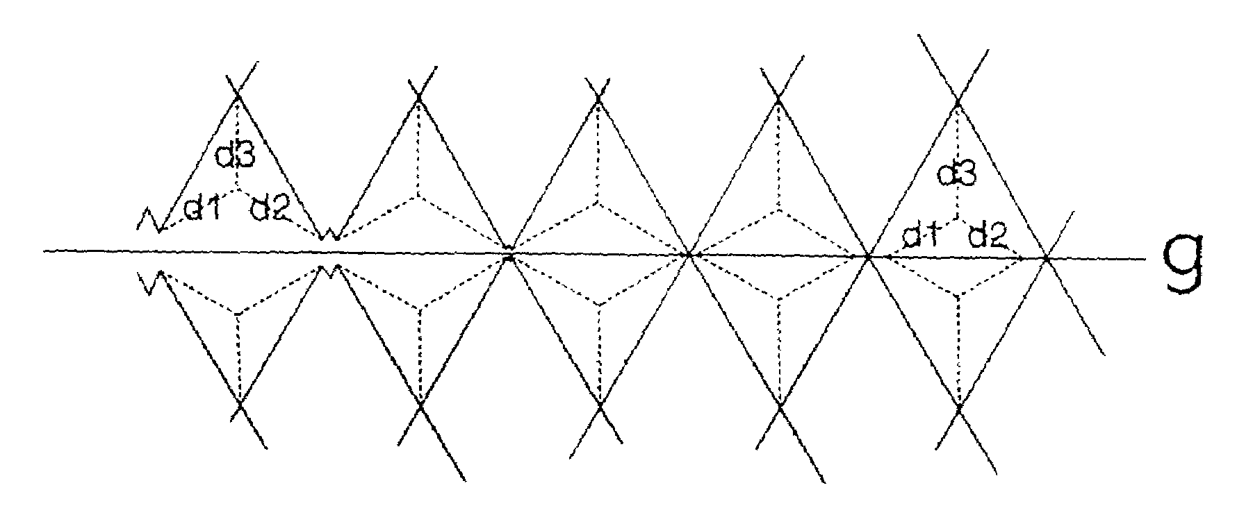
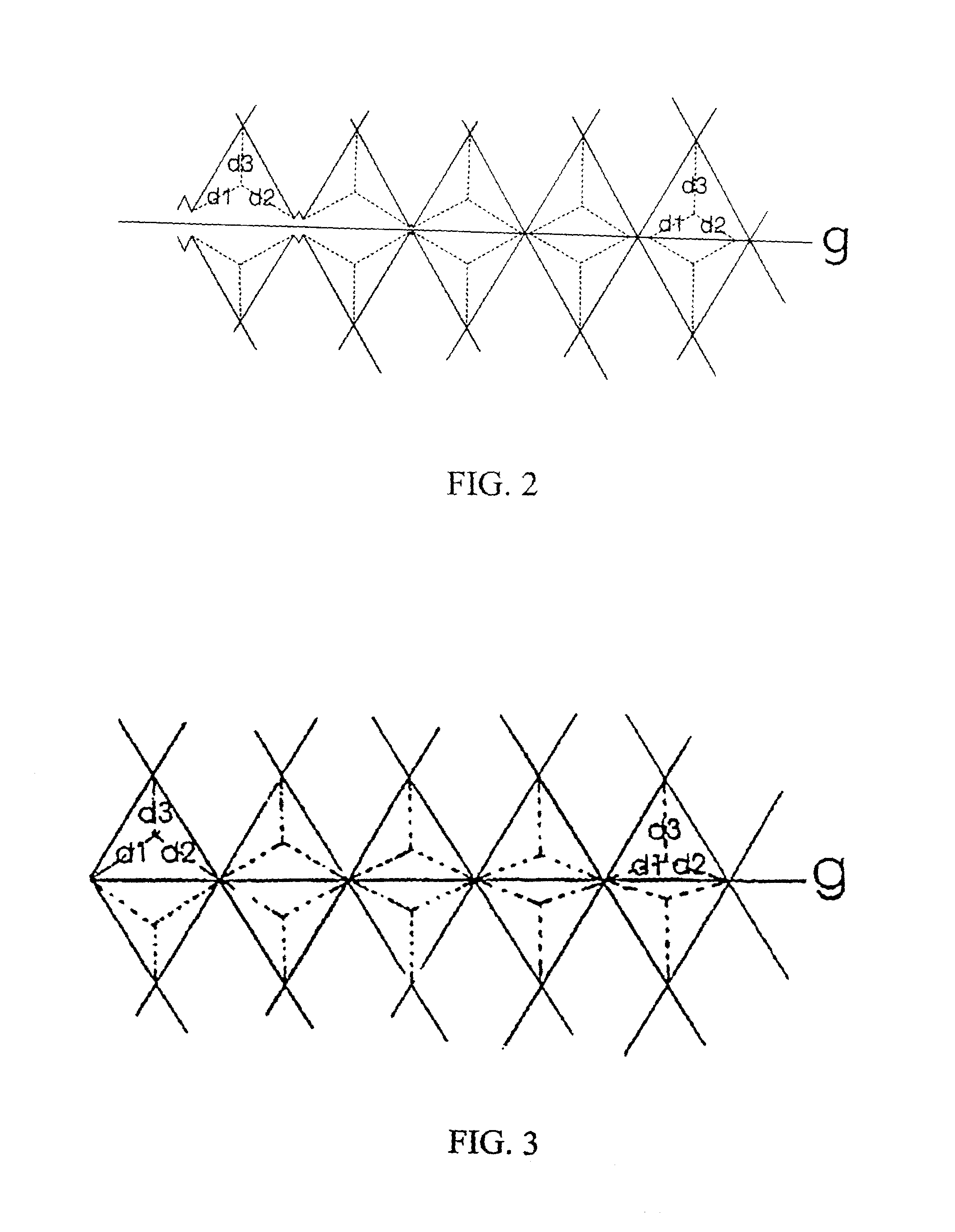
[0073]Examples 3–6 illustrate rulings that can be made in accordance with the instant inventi...

example 3

[0075]For Example 3 sinusoidal vertical undulation is assumed according to Mode 1 of this invention. Ruling dimensions are shown in Table 2 under 20[sin]. FIG. 6A shows the resulting calculated diffraction pattern. It has a gentle central peak and is uncluttered with diffraction and aberration artifacts out to about 2° observation angle. This is the beneficial result of the cube corners not being alike as they were in Examples 1 and 2. FIG. 9 shows the observation angularity of Example 3 as curve 20[sin]. Its intensity at 1.1° is only 37% that of prior art Example 2 at 1.1°. However its intensity at 0° is 16 times that of prior art Example 2, and its intensity at 2° is 2.2 times that of prior art Example 2. Unlike Example 2, a retroreflector having the aberrated cube corners of Example 3 is not limited to close applications, but performs well over a broad distance range.


PUM

PropertyMeasurementUnit
Fractionaaaaaaaaaa
Lengthaaaaaaaaaa
Lengthaaaaaaaaaa

Abstract

A ruling of cube corner elements comprising intersecting ruled vee-grooves is characterized in that at least one of the vee-grooves is made such the substrate being ruled and the cutting tool are oscillated with respect to one another during the ruling of the vee-groove. Rulings made in accordance with the instant invention can be designed to produce a cube corner element having broader divergence.

Description

[0001]This patent application claims the benefit of U.S. Provisional Application No. 60 / 297,394 filed Jun. 11, 2001.BACKGROUND OF THE INVENTION[0002]This invention relates to a method of making a retroreflective article having controlled divergence, and articles made by the method.[0003]It is well known that retroreflective articles can be made from an array of microcube corner elements. Such an array of microcube corner elements can be made by ruling a master of “male” cube corners into a planar surface of a plate. This is taught generally by Stamm U.S. Pat. No. 3,712,706; and also is taught in detail in Pricone U.S. Pat. No. 4,478,769. Each of these patents is incorporated herein by reference in its entirety.[0004]U.S. Pat. No. 4,478,769 describes a well-known method of making triangular cube corner elements, in which the planar surface of a master plate is ruled with a diamond cutting tool that cuts a series of precise parallel vee-grooves. To rule equilateral triangular cube cor...

Claims


Application Information

Patent Timeline
IPC IPC(8): G02B5/124B29D11/00G02B5/122
CPCB29D11/00605G02B5/124G02B5/122B29C2793/00Y10T428/2457Y10S359/90
Inventor COUZIN, DENNIS I.SANDLER, LEGAL REPRESENTATIVE, RONALD A.HEENAN, DECEASED, SIDNEY A.
Owner AVERY DENNISON CORP
Why Eureka
Try Eureka