Portable luminaire

a technology of airfield lighting and portability, which is applied in the direction of landing aids, instruments, roads, etc., can solve the problems of limited operation time on this second system without recharging, heavy and bulky luminaires, and bulky systems, and achieve wide divergence, high efficiency, and high efficiency

Inactive Publication Date: 2008-08-14
FARLIGHT
View PDF74 Cites 7 Cited by
  • Summary
  • Abstract
  • Description
  • Claims
  • Application Information

AI Technical Summary

Benefits of technology

[0013]According to yet another aspect of the invention, an optical module includes at least one light emitting diode (LED) that emits light with a wide divergence, a non-imaging optical element and a transparent window. The non-imaging optical element (NIO) includes a refractive member located around a LED optical axis and a total internal reflection member located around the refractive member, wherein the refractive member and the total internal reflection member are integrated in a single transparent element having a mutual focal point, wherein the NIO element collects a significant amount of light emitted by the LED with wide divergence located at the focal point, to compress the collected light with high efficiency into a required pattern with a generally different angular distribution in a horizontal plane and a vertical plane, and to direct the compressed light outside of a luminaire. The transparent window transmits light outside of the luminaire.
[0014]According to another aspect of the invention, a portable luminaire includes an optical module and a power source. The optical module includes multiple LEDs, a non-imaging optical element and a transparent window. The multiple LEDs emit light with a wide divergence. The NIO element includes a refractive member located around a LED optical axis and a total internal reflection member located around the refractive member, wherein the refractive member and the total internal reflection member are integrated in a single transparent element having a mutual focal point, wherein the NIO element collects a significant amount of light emitted by the LEDs with wide divergence located at the focal point, to compress the collected light with high efficiency into a required pattern with a generally different angular distribution in a horizontal plane and a vertical plane, and to direct the compressed light outside of the luminaire. The transparent window transmits light outside of the luminaire. The autonomous rechargeable power source includes a connector to connect to an outside charger

Problems solved by technology

Unfortunately, this type of system is bulky, typically weighs in excess of 30,000 lbs, is packaged in six containers requiring 48 foot flatbed trailers for transportation, and requires a team of six people for installation that often takes over three hours.
Even though this type of system does not require the elaborate infrastructure associated with the first system, the luminaries are still heavy and bulky because they include two lead acid 12v batteries.
Additionally, the operation time on this second system without recharging is limited to 8-10 hours.
Finally, high intensity approach lights cannot be operated from the battery but rather require the use of a generator.
The luminous intensity required for airfield lights varies from several candelas to in excess of 10,000 candelas, which makes implementing LEDs into portable airfield lighting systems extremely difficult.
For example, in order to use LEDs in a system, the luminous flux generated by a single LED is still limited, thereby necessitating the combination of multiple LEDs.
Unfortunately, practical implementation of a multiple LED system has not been realized because of this reliance on a specific primary optic design.
In general, a primary optic with low divergence has more losses (e.g., it is less efficient).

Method used


Image

  • Portable luminaire
  • Portable luminaire
  • Portable luminaire

Examples


Embodiment Construction

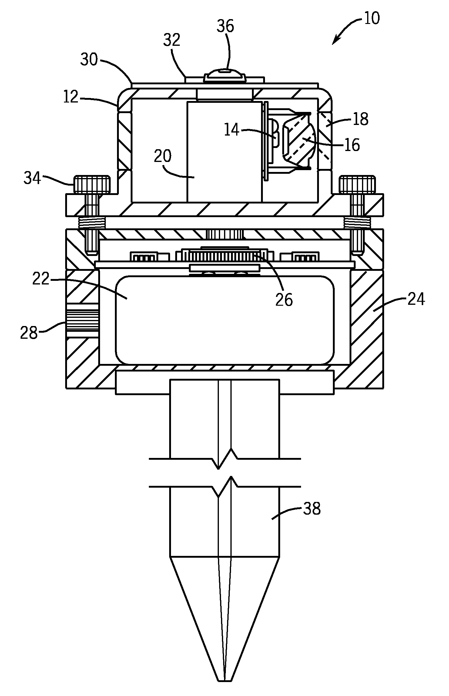
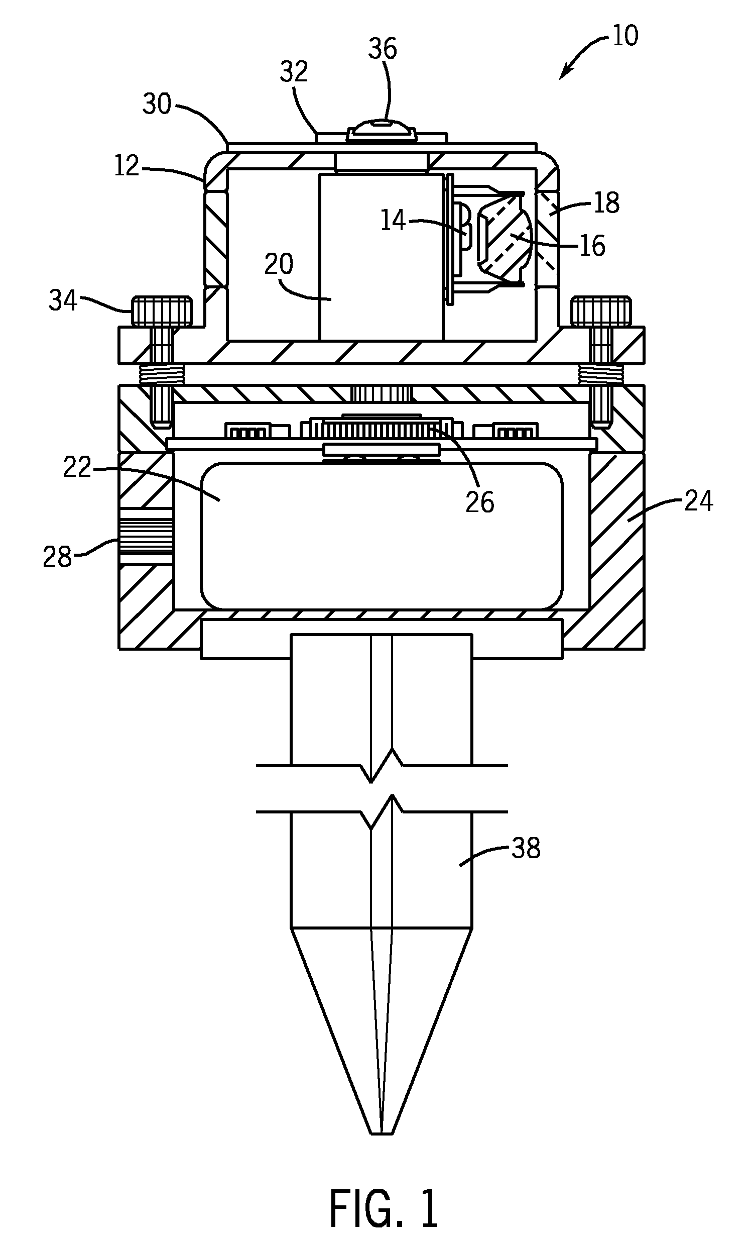
[0025]Referring now to FIG. 1, a deployable airfield luminaire 10 includes an optical module 12 having a light emitting diode (LED) 14 for emitting light with a wide divergence, and a non-imaging optical element 16 to compress the emitted light into a desired pattern. Module 12 further includes a transparent window 18 to transmit compressed light outside luminaire 10.

[0026]A base 20 is a heat sink for LED 14 and a holder for non-imaging optical element 16. A rechargeable power source 22 is installed in a housing 24 and connected to LED 14 through a controller 26 to an outside charger (not shown) through a connector 28 and to a solar element 30 located on the top of optical module 12 (connection not shown).

[0027]Controller 26 includes conventional electronics to provide remote control operation through a sensor 32.

[0028]Housing 24 includes a leveling mechanism 34 that adjusts luminaire 10 with respect to the horizontal surface using an aiming indicator 36. An installation hardware sy...


PUM


Abstract

A portable luminaire includes an optical module, a power source and a housing. The optical module has at least one light emitting diode (LED) that emits light with a wide divergence, a non-imaging optical element and a transparent window. The non-imaging optical element (NIO) has a refractive member located around a LED optical axis and a total internal reflection member located around the refractive member. The refractive member and the total internal reflection member are integrated in a single transparent element having a mutual focal point. The NIO element collects a significant amount of light emitted by the LED with wide divergence located at the focal point to compress the collected light with high efficiency into a required pattern with a generally different angular distribution in a horizontal plane and a vertical plane, and to direct the compressed light outside of the luminaire.

Description

CROSS-REFERENCE TO RELATED APPLICATION[0001]This application is a continuation of and claims priority to U.S. patent application Ser. No. 10 / 277,230, filed Oct. 21, 2002; which is a continuation-in-part of U.S. patent application Ser. No. 09 / 566,521, filed May 8, 2000, now U.S. Pat. No. 6,543,911.BACKGROUND OF THE INVENTION[0002]1. Field of Invention[0003]The present invention relates generally to luminaries for airfield lighting. In particular, the present invention relates to deployable elevated luminaries for portable airfield and heliport applications including omnidirectional runway edge lighting, threshold and stop bars, and unidirectional approach lights.[0004]2. Discussion of Relevant Prior Art[0005]The distinctive property of portable airfield lighting is the absence of power infrastructure on the site. There are currently two types of systems available for portable airfield lighting using conventional light sources. The first type of system includes a deployable version of...

Claims


Application Information

Patent Timeline
Patent Type & Authority Applications(United States)
IPC IPC(8): F21V7/00F21V5/00F21V5/04B64F1/20E01F9/06F21K99/00F21S2/00F21S8/00F21V7/04F21V7/06F21W111/06F21Y101/02G08B5/00
CPCB64C2027/8236B64F1/20E01F9/065F21S10/06F21V5/046F21V7/0008Y10S362/80F21V7/04F21V21/0824F21W2111/06F21Y2101/02F21V13/04F21V7/0091B64F1/205E01F9/559F21Y2103/33F21Y2115/10B64D2203/00
Inventor RIZKIN, ALEXANDERTUDHOPE, ROBERT H.
Owner FARLIGHT
Why Eureka
Try Eureka