Selectively-extendable modular lighting fixture and method

a modular and fixture technology, applied in the field of modular lighting fixtures, can solve the problems of not being able to adapt to the varying physical configuration, the inability of conventional lighting fixtures to adapt to the varying length and physical configuration, and the inability of conventional structures and lighting methods to selectively implement fixtures having different shapes

Inactive Publication Date: 2006-01-10
KENALL MFG
View PDF24 Cites 52 Cited by
  • Summary
  • Abstract
  • Description
  • Claims
  • Application Information

AI Technical Summary

Benefits of technology

[0006]Another object of the invention is to provide a modular lighting system easily adaptable for creating different shapes and configurations in linear lighting applications.
[0009]Yet another object of the invention is to provide a modular lighting system that allows a designer to implement linear lighting using any number of modules having selectable lengths.
[0025]As a result of implementing certain aspects of the invention, lighting fixtures may be characterized as providing “selectably extendable and angularly-directable linear lighting.” For example, by joining a number of modules, sections, or housing components to one another at end portions or segments thereof, a lineal array of selectable length or lineal expanse may be provided as required or desired. Alternatively, the fixture may consist of two linear arrays connected at ends thereof to define an angle, for example a 90 degree juncture or corner. In another example, lineal sectors or sections may be oriented with respect to one another to provide various different geometric configurations or shapes. Accordingly, a large variety of lighting design choices may be implemented efficiently. In addition, a structure according to the invention also provides fluid-impervious sealing.

Problems solved by technology

Traditional lighting fixtures are not readily adaptable for adjusting length and changing physical configuration.
In particular, conventional structures and lighting methods are not adapted for selectively implementing fixtures having different shapes.

Method used


Image

  • Selectively-extendable modular lighting fixture and method
  • Selectively-extendable modular lighting fixture and method
  • Selectively-extendable modular lighting fixture and method

Examples


Embodiment Construction

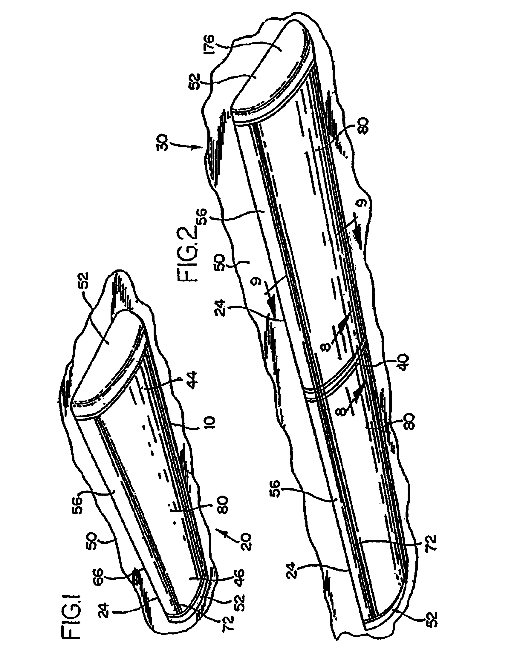
[0040]FIG. 1 is a perspective view of a lighting fixture module 24 that may be configured in any of several different forms, in this case being configured as a single module fixture 20 by adding endcaps 52. Module 24 may also be referred-to herein as “housing section 24” that includes a body section 10 and a pair of end plates 34. Module 24 may also include a lens 80.

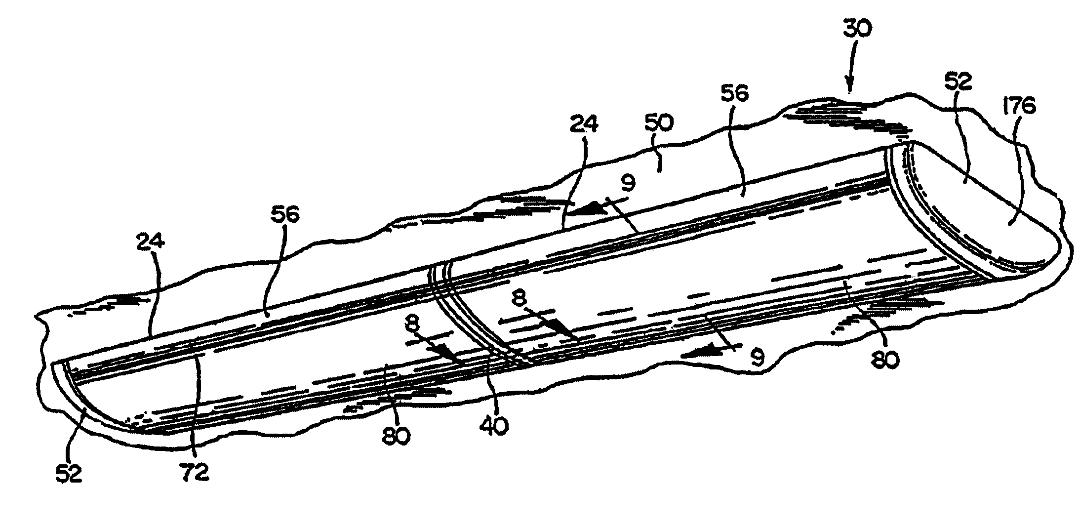
[0041]FIG. 2 shows a dual-module lighting fixture 30 having two housing sections 24. The two housing sections 24 of fixture 30 are secured end-to-end to one another at respective facing end plates 34 thereof (e.g., FIGS. 3–5, 7, 8), by a coupler 40 interposed between the respective end plates 34.

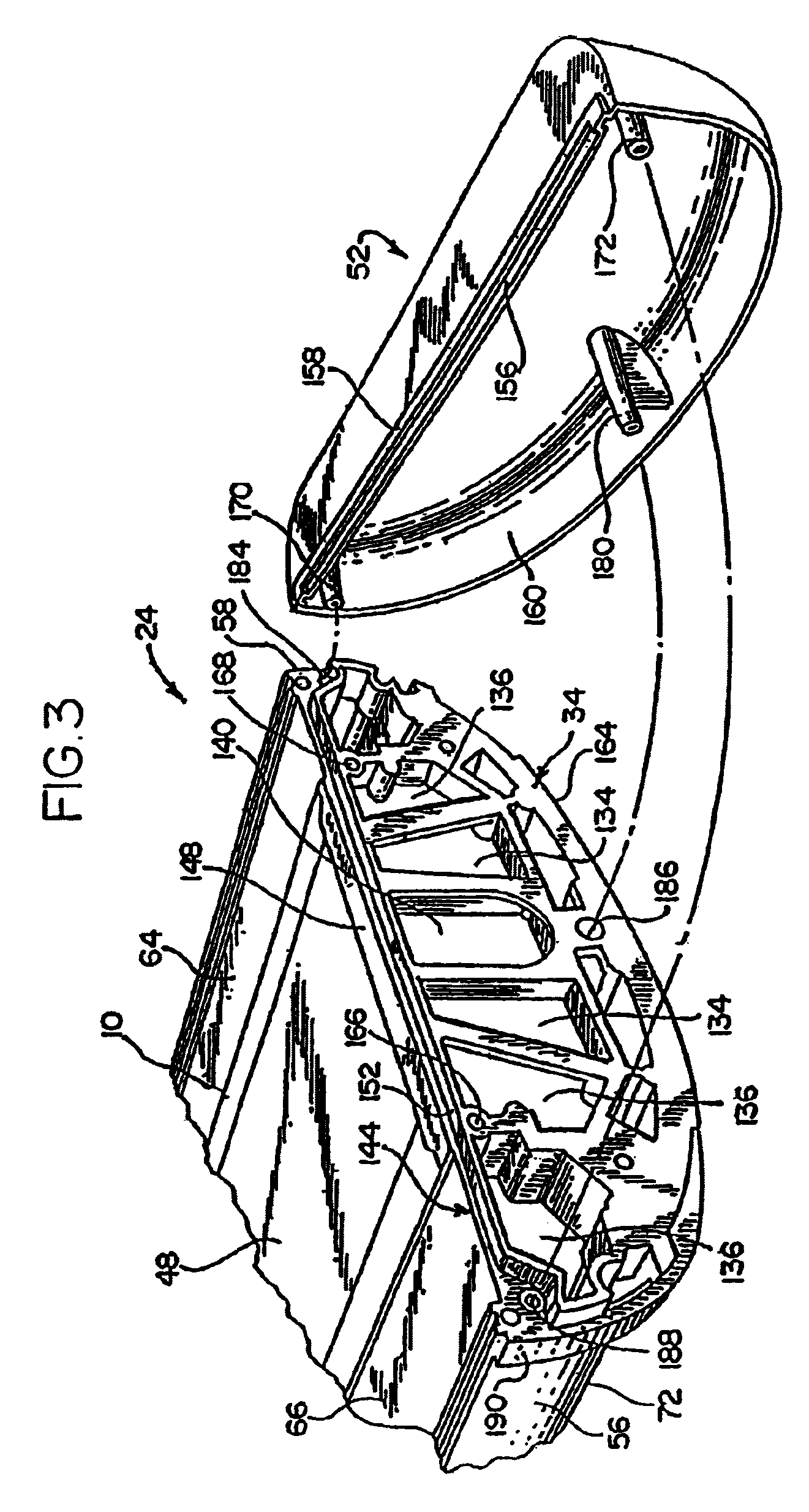
[0042]Either fixture 20, 30 may be securely mounted at respective generally planar bases 48 thereof to a ceiling or similar structure 50. Free ends of housing section 24 may be sealed at end plates 34 thereof with fitted end caps 52. End cap 52 abuts and is securely mounted to end plate 34, as shown by way of example in FIG. 3. ...


PUM

PropertyMeasurementUnit
angleaaaaaaaaaa
perimeteraaaaaaaaaa
perimeter surfacesaaaaaaaaaa

Abstract

A modular, linear-type lighting fixture may include an elongate housing having lengthwise ends, and a pair of endplates adapted for sealing attachment to either lengthwise end of the housing, each of the endplates having respective perimeter surfaces adapted for attachment to any one of a bridge adapted for angularly-directable extension of the housing, a bridge adapted for linear extension of the housing, and an endcap. A modular lighting fixture may include first and second elongate housings each having ends, pairs of endplates for being respectively mated with the first and second ends of the first and second elongate housings, the endplates each having a rim, and a bridge adapted for joining one of the endplates of the first elongate housing with one of the endplates of the second elongate housing by sealing cooperation with the respective rims thereof. A lighting fixture may have one or more isolated raceways therein.

Description

RELATED APPLICATIONS[0001]The present application is a continuation of patent application Ser. No. 10 / 156,423, filed May 28, 2002, now abandoned.FIELD OF THE INVENTION[0002]The invention relates generally to a lighting fixture and, more particularly, to a modular lighting fixture adaptable for being implemented in various shapes and configurations.BACKGROUND OF THE INVENTION[0003]Many different types of lighting fixtures, including elongate fixtures for various applications and locations, are known in the art. Such fixtures have been installed for illuminating stores, offices, supermarkets, schools, hospitals, banks, and other interior and exterior areas. Appreciating the versatility of such lighting fixtures, including the many engineering designs and configurations, there remains a need for improving versatility and adaptability of a lighting fixture, in order to facilitate and enhance particular applications.[0004]Traditional lighting fixtures are not readily adaptable for adjust...

Claims


Application Information

Patent Timeline
Patent Type & Authority Patents(United States)
IPC IPC(8): F21S8/06F21V15/015F21V21/005F21V27/00
CPCF21S2/00F21V15/015F21V21/005F21S2/005F21V21/14F21Y2103/00F21S8/04F21V27/00B29D21/04F21V3/02F21V17/10F21V17/12F21V31/005
Inventor MCCARTHY, CHARLES A.KELLY, JAMES P.
Owner KENALL MFG
Why Eureka
Try Eureka