
Lavatory system

a technology of lavatory system and lava chamber, which is applied in the field of lavatory system, can solve the problems of inconvenient or disadvantageous lavatory system

Inactive Publication Date: 2006-01-17
BRADLEY FIXTURES
View PDF92 Cites 39 Cited by
  • Summary
  • Abstract
  • Description
  • Claims
  • Application Information

AI Technical Summary

Benefits of technology

[0008]The present invention further relates to an apparatus for a lavatory system having a commode with a front and a rear coupled to a base and configured to pivot between a deployed position and a stowed position, and a detent engaged between the commode and the base. The apparatus comprises a member adjacent the front of the commode and operatively coupled to the detent, the member configured to disengage the commode from the base by actuation of the detent so that the commode can be moved from the deployed position toward the stowed position.

Problems solved by technology

However, such known arrangements for lavatory systems may present inconvenient or disadvantageous features in application or use, such as relative difficulty to use (e.g., effort and vigilance to stow or cover toilet), or to clean (or keep clean), or to maintain the mechanism that disengages the toilet from its locked position.

Method used


Image

  • Lavatory system
  • Lavatory system
  • Lavatory system

Examples


Embodiment Construction

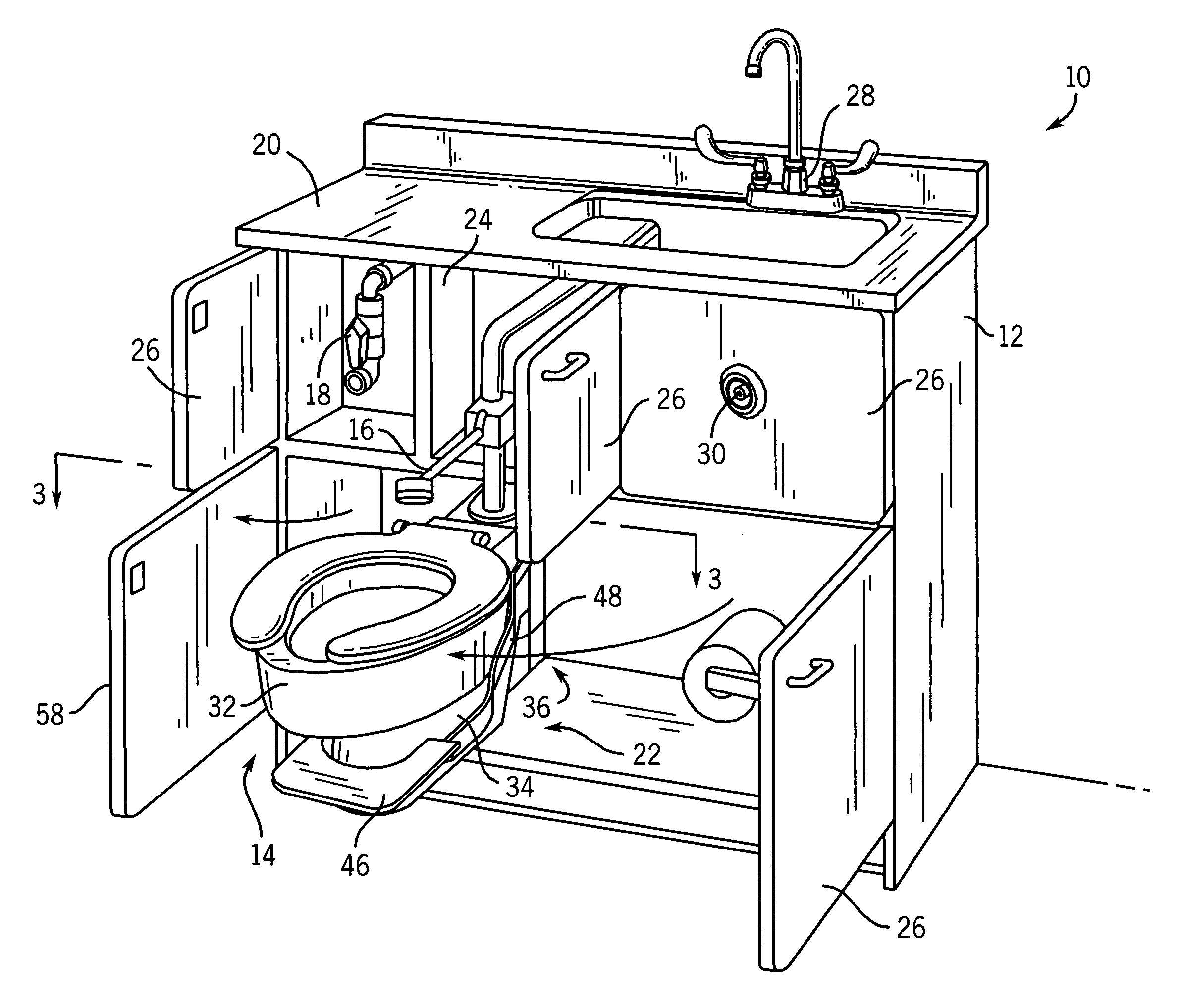
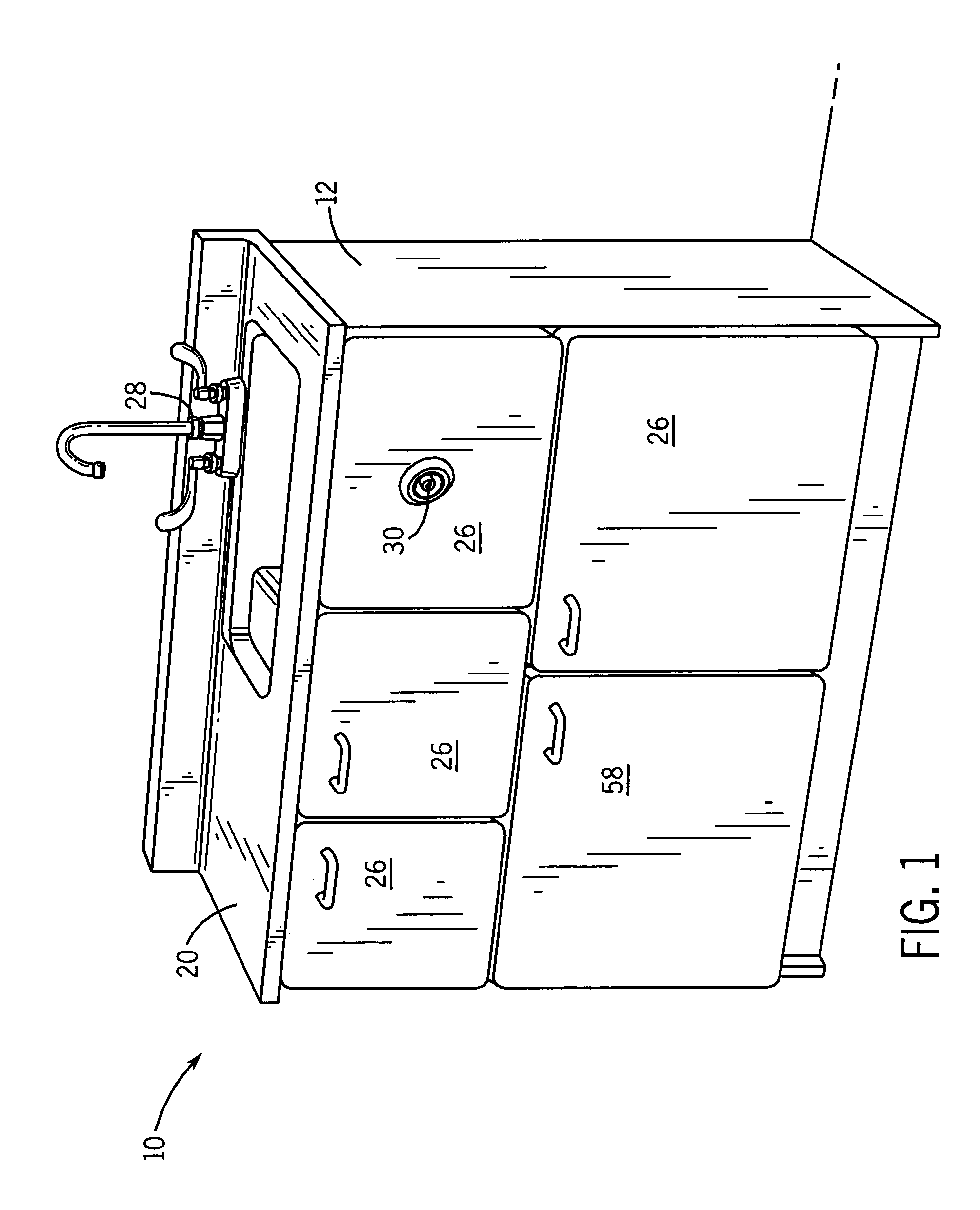
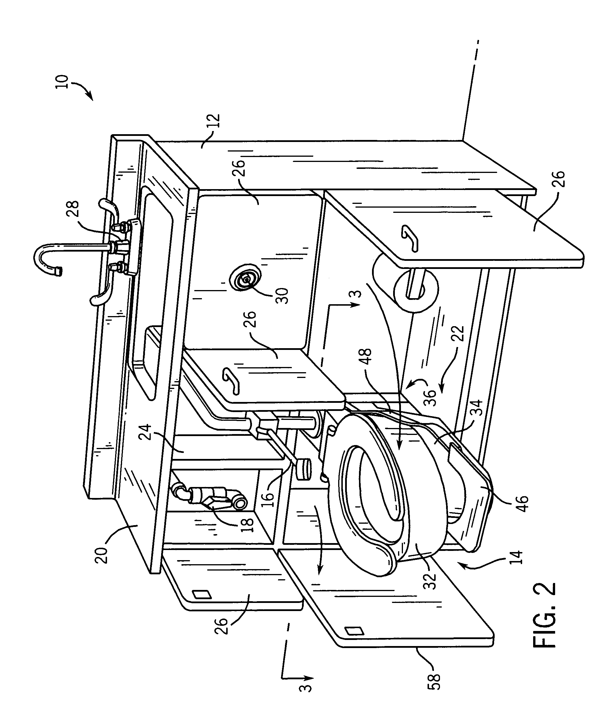
[0022]The FIGURES disclose a lavatory system 10 according to a preferred embodiment. Lavatory system 10 includes a base shown as a cabinet 12, a receptacle shown as a commode 14, one or more accessories (e.g., bedpan washer 16, dialysis apparatus 18, etc.), a countertop 20 mounted to cabinet 12, and a release assembly or mechanism 22.

[0023]Cabinet 12 includes a structural frame 24 and a plurality of panels 26 mounted on frame 24 or pivotally coupled to the base shown as cabinet 12. Frame 24 is configured to support cabinet 12 and includes a plurality of support members (e.g., horizontal braces or members and vertical braces or members). The support members are connected by any of a variety of fabrication methods such as fasteners, welding, riveting, etc. A plumbing system for lavatory system 10 is generally enclosed by cabinet 12 and is in communication with commode 14, a faucet assembly 28, and the accessories. A valve interface (shown as a flush button 30) is mounted to cabinet 12...


PUM


Abstract

A lavatory system is disclosed. The lavatory system comprises a base, a commode having a front and a rear coupled to the base and movable relative to the base between a deployed position and a stowed position, a first projection engaged between the base and the commode, and a first member adjacent the front and coupled to the projection so that the commode can be disengaged from the base. An apparatus for a lavatory system is also disclosed. The lavatory system has a commode with a front and a rear coupled to a base and configured to pivot between a deployed position and a stowed position, and a detent engaged between the commode and the base. The apparatus comprises a member adjacent the front of the commode and operatively coupled to the detent, the member configured to disengage the commode from the base by actuation of the detent so that the commode can be moved from the deployed position toward the stowed position.

Description

CROSS-REFERENCE TO RELATED PATENT APPLICATIONS[0001]The present invention claims priority under 35 U.S.C. § 119 to U.S. Provisional Patent Application No. 60 / 376,168 titled “LAVATORY SYSTEM” filed Apr. 26, 2002, the full disclosure of which is hereby incorporated herein by reference.BACKGROUND OF THE INVENTION[0002]The present inventions relate to a lavatory system. The present inventions more specifically relate to a lavatory system including a toilet and a mechanism movable between a stowed position and a deployed position.[0003]It is generally known to provide for a lavatory system for use in a home, commercial or institutional facility such as a medical care facility or the like. Known arrangements for lavatory systems may provide (in a compact design) a base (e.g. cabinet), a sink, water closet (i.e., with toilet), countertop, and may be configured with one or more accessories such as a bedpan washer, dialysis equipment, etc. Such lavatory systems may be configured to provide a...

Claims


Application Information

Patent Timeline
IPC IPC(8): E03D11/12
CPCE03D11/12
Inventor PERRIN, TIMOTHY E.
Owner BRADLEY FIXTURES
Learn More