Visual display attachment to ski lift equipment

Inactive Publication Date: 2006-01-17
SPINVISION
View PDF25 Cites 14 Cited by
  • Summary
  • Abstract
  • Description
  • Claims
  • Application Information

AI Technical Summary

Benefits of technology

[0006]The purpose of the present invention is to provide an information display device that: protects the information to be displayed against tampering and the elements; is easy to rotate about the cy

Problems solved by technology

However, the known display devices are not well constructed to protect the information being displayed against the elements, such as blizzards.

Method used


Image

  • Visual display attachment to ski lift equipment
  • Visual display attachment to ski lift equipment
  • Visual display attachment to ski lift equipment

Examples


Embodiment Construction

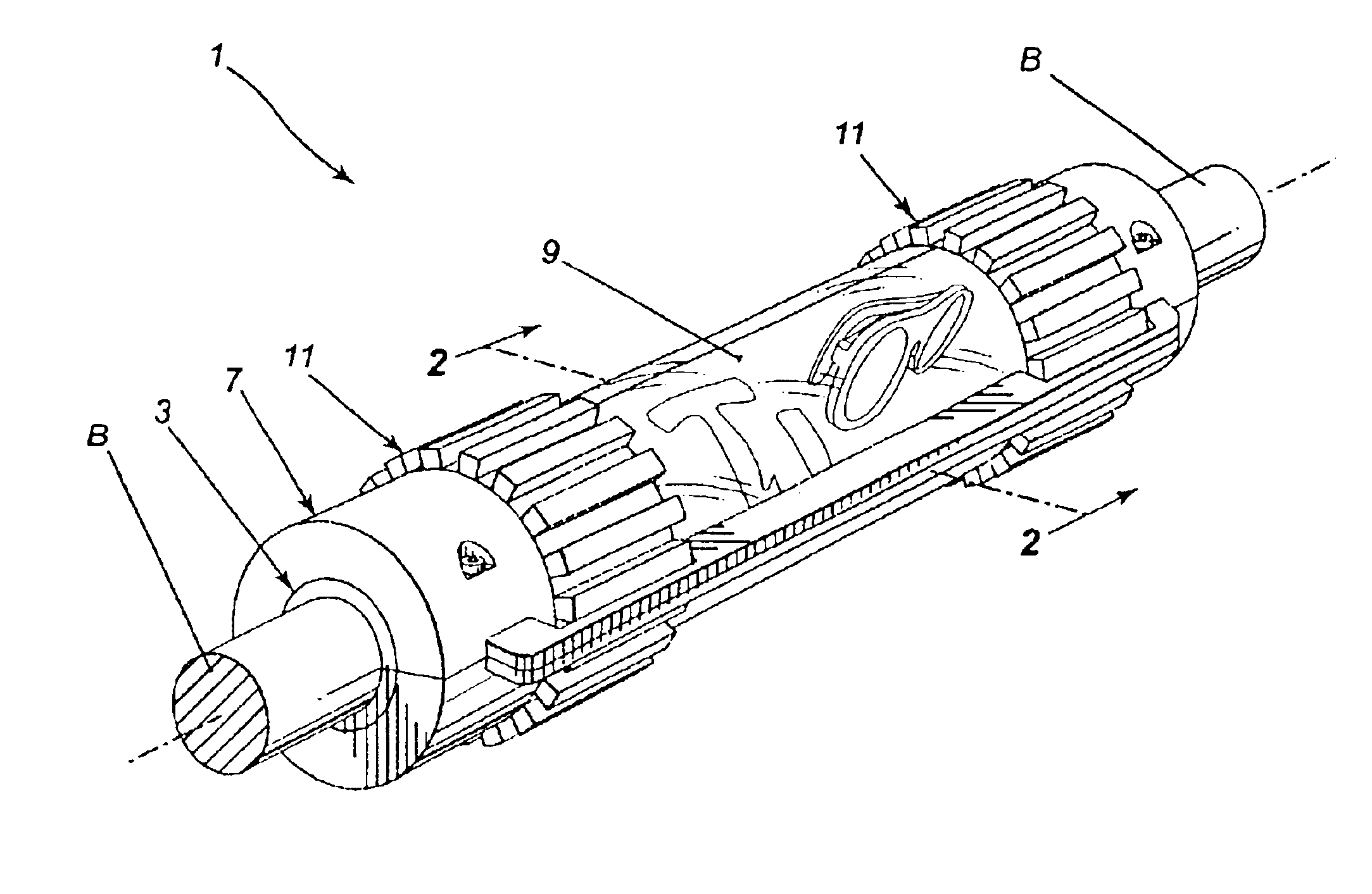
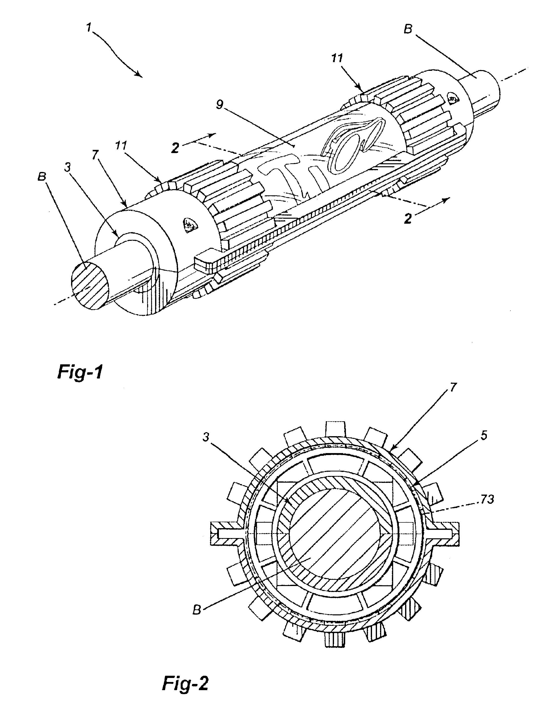
[0024]The display device 1 of the present invention, as shown in FIGS. 1 and 2, has a tubular base 3 that fixedly mounts onto a safety bar B on a ski-lift chair. The device includes a tubular carrier 5 that is rotatably mounted on the base 3, the carrier 5 carrying the information to be displayed by the device; and a tubular cover 7 overlying the carrier 5 to protect the information it carries, the cover 7 fixedly attached to the base 3. At least a portion 9 of the cover 7 is transparent to allow viewing of the information carried by the carrier 5. The device 1 includes rotation means 11 for rotating the carrier 5 about the base 3 to display all the information carried by it through the transparent portion 9 on the cover 7.

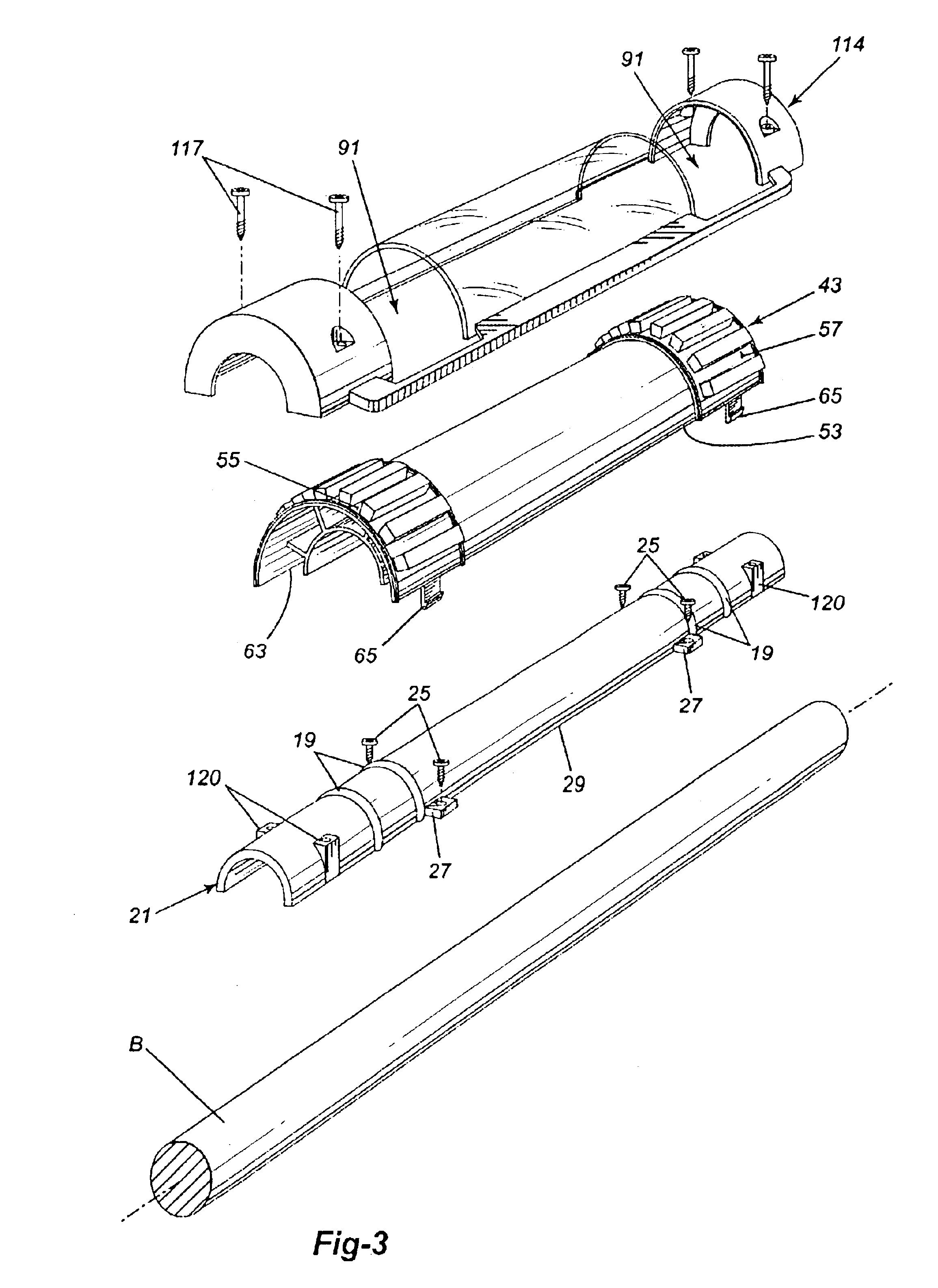
[0025]In more detail, as shown in FIGS. 3 to 5, the base 3 of the device 1 is in the form of an elongate, tubular member. A pair of spaced-apart guide tracks 15, 17 encircle the base 3. Each guide track 15, 17 is defined by a pair of spaced-apart guide ribs 19 enc...


PUM


Abstract

An information display device adapted to be mounted on the safety bar of a ski-lift chair. The device has a tubular base which is rigidly attached to the safety bar. A tubular carrier is rotatabley secured to the tubular base. This tubular carrier provides a cylindrical support surface for information to be displayed. A tubular cover is mounted about the carrier and fixed to the tubular base to protect the tubular carrier and the information attached to it.

Description

BACKGROUND OF THE INVENTION[0001]1. Field of the Invention[0002]This invention is directed toward an information display device adapted to be mounted on a cylindrical support such as a bar. The invention is particularly directed toward a display device for mounting on the safety bar of a ski-lift chair.[0003]2. Description of the Related Art[0004]Display devices rotatably mounted on cylindrical bars are known. One such known device, mounted on the safety bar of a ski-lift chair, is shown by U.S. Pat. No. 5,685,095.[0005]However, the known display devices are not well constructed to protect the information being displayed against the elements, such as blizzards. Further, the known devices are not very securely mounted to prevent tampering with the device and / or with the information carried by the device.SUMMARY OF THE INVENTION[0006]The purpose of the present invention is to provide an information display device that: protects the information to be displayed against tampering and the...

Claims


Application Information

Patent Timeline
IPC IPC(8): G09F11/02G09F3/20G09F23/02
CPCG09F23/02G09F3/20
Inventor KAULBACH, NICHOLAS R. M.
Owner SPINVISION
Why Eureka
Try Eureka