Remote operated vehicles
What is Al technical title?
Al technical title is built by PatSnap Al team. It summarizes the technical point description of the patent document.
a remote-operated, vehicle technology, applied in the direction of inductance, coupling device connection, underwater equipment, etc., can solve the problems of difficult manhandling of the power supply and umbilical cable for transmitting power from the surface to the fish, and the general mass of commercial rovs
Inactive Publication Date: 2006-01-17
H2EYE INT
View PDF44 Cites 49 Cited by
Summary
Abstract
Description
Claims
Application Information
AI Technical Summary
This helps you quickly interpret patents by identifying the three key elements:
Problems solved by technology
Method used
Benefits of technology
Problems solved by technology
Commercial ROVs are generally very massive, and therefore cannot be transported from location to location by a single person.
However, even with a smaller fish, the power supply together with the umbilical cable for transmitting the power from the surface to the fish are still difficult to manhandle.
However, high power loads such as those required to drive the thrusters on the fish will not be transmittable, other than at very high voltages.
This prevents the magnetic core remaining “live” unnecessarily; high power magnetic fields may be hazardous if not contained in a magnetic core.
This would be impractical for recreational ROVs since the user would not necessarily have diving equipment.
Under high pressure, a scratch in the first layer would increase the probability of the layer failing.
Method used
Image
Click on the blue label to locate the original text in one second.
Reading with bidirectional positioning of images and text.
Examples
Embodiment Construction
The ROV
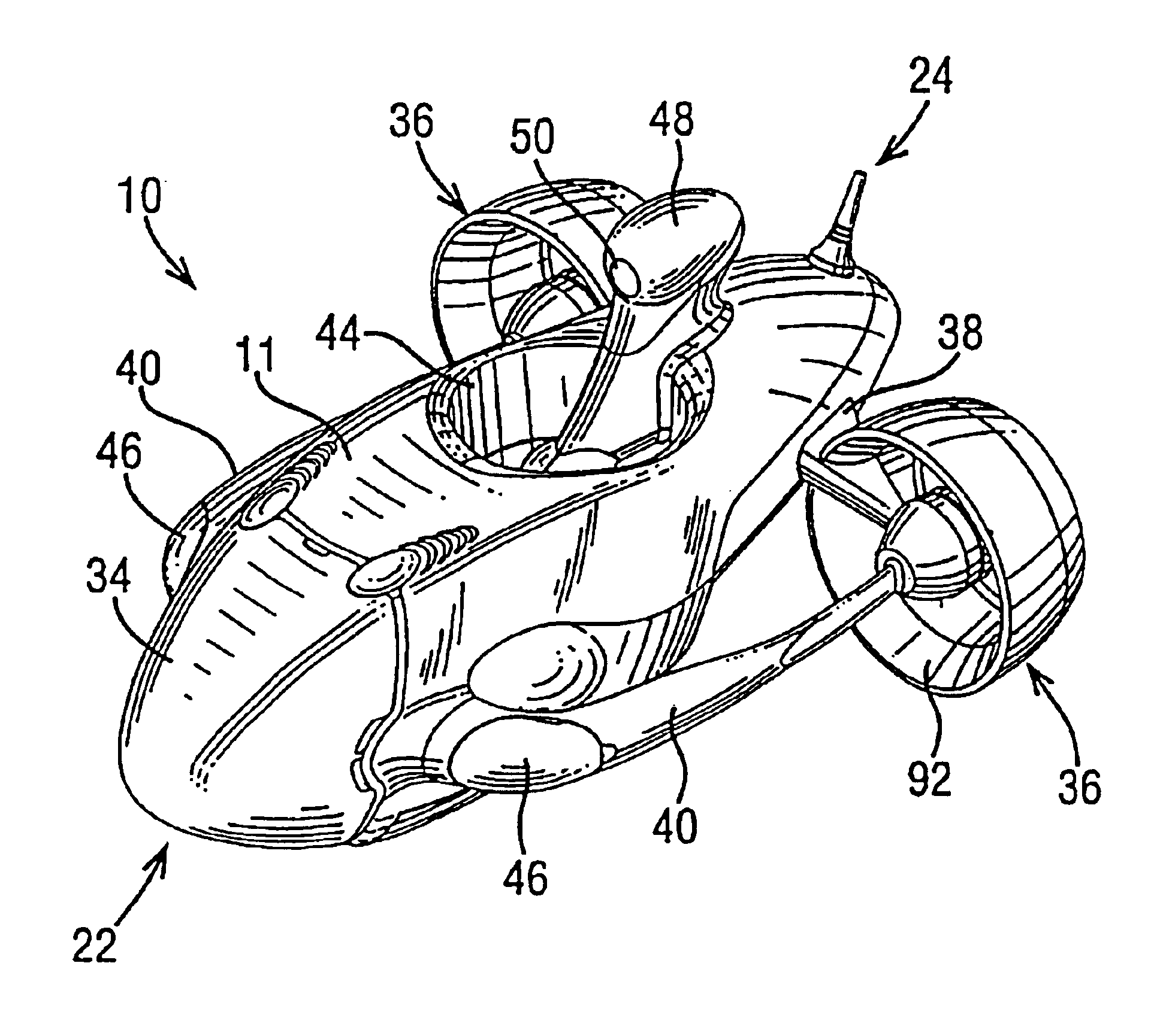
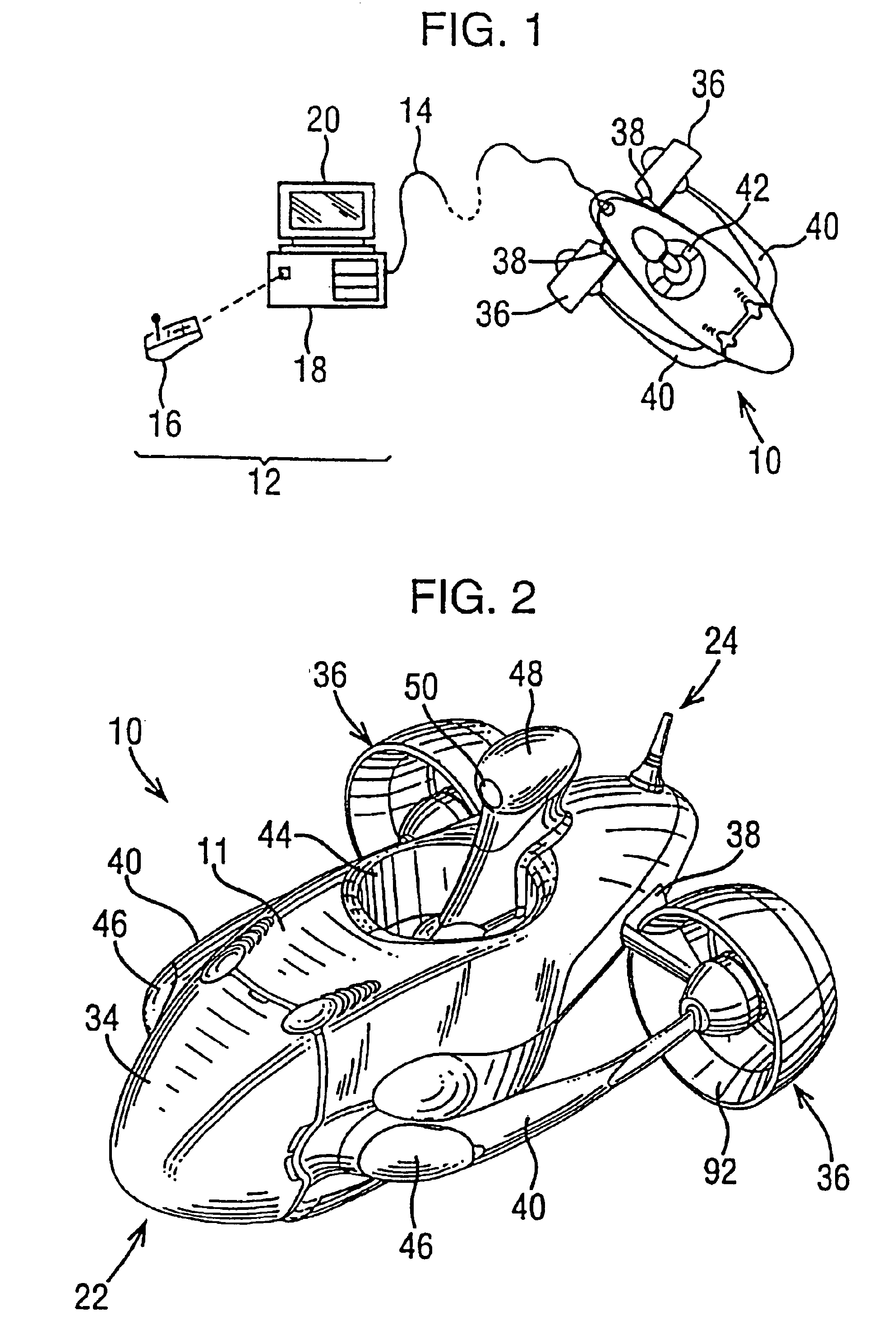
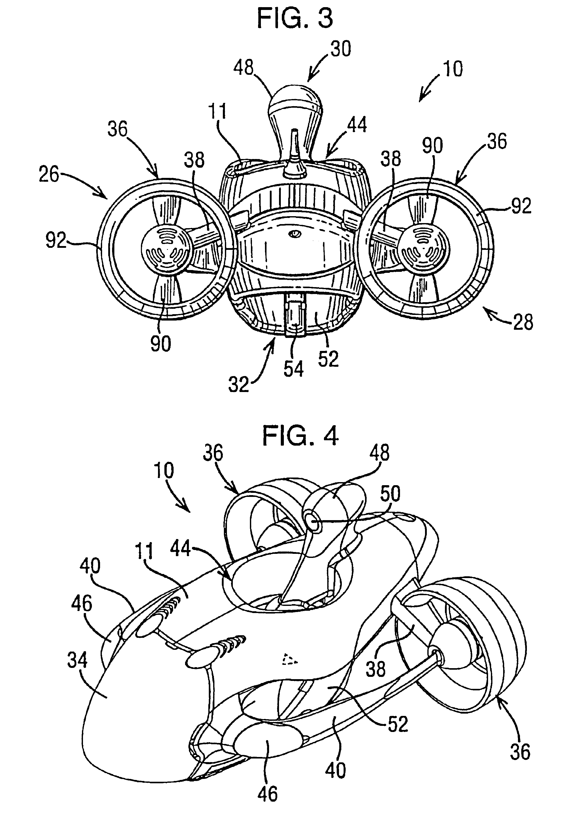
[0069]Referring to FIGS. 1 to 4 there is shown an ROV kit in accordance with the present invention. The ROV is a collection of units which together perform the function of an underwater remotely controlled television camera. The ROV kit comprises two main units, these being the underwater unit or “fish”10, and the surface control unit or “topside”12. Joining the two main units is a cable or “umbilical cable”14. The cable 14 is preferably at least 200 m long and accordingly is , for ease of handling, generally wound onto a winder, not shown.
The Topside 12
[0070]The topside 12 comprises a wireless handset 16 and a computer unit 18. During the deployment operations of a fish 10, there are different activities such as launch, depth deployment and recovery of the fish 10 from the water. For these different operations, the operator may need to be in a different place or may need to move about the zone in which the operations take place. The wireless handset makes this easy and safe ...
PUM
Property
Measurement
Unit
diameter
aaaaa
aaaaa
depth
aaaaa
aaaaa
mass
aaaaa
aaaaa
Abstract
An ROV comprising a topside, a fish and an umbilical cable for connecting the topside and the fish together. The fish is adapted to be powered by an onboard battery inductively coupled to the fish. The cable is of a fine diameter to reduce drag through the water. RF transmissions carry control and return signals to and from the fish and topside. The fish has two cameras. The front facing camera is located behind a dual layer flooded dome. A pan and tilt mechanism is fitted to one of the cameras and uses a pivotable gimbal frame driven by a lead nut moving along an arcuate bolt.
Description
[0001]This application is a divisional of U.S. patent application Ser. No. 09 / 928,258 filed on Aug. 10, 2001 now U.S. Pat. No. 6,662,742, which is hereby incorporated herein by reference in its entirety, and which is a continuation-in-part of International Application No. PCT / GB01 / 00527, filed on Feb. 9, 2001 and published in English.BACKGROUND OF THE INVENTION[0002]The present invention relates to remote operated vehicles or ROVs, and in particular to ROVs for use in exploration of an underwater environment.[0003]Conventional ROVs are typically used by commercial enterprises and comprise a “submarine” unit or vehicle (the fish), a landbased remote control unit (the topside) connected to a power source such as a generator or power cells, and an umbilical cable connecting the two units together for transmitting power and control signals from the topside to the fish.[0004]The fish is usually fitted with swimming means, such as motor driven propellers, for maneuvering the fish underwat...
Claims
Application Information
Patent Timeline
Application Date:The date an application was filed.
Publication Date:The date a patent or application was officially published.
First Publication Date:The earliest publication date of a patent with the same application number.
Issue Date:Publication date of the patent grant document.
PCT Entry Date:The Entry date of PCT National Phase.
Estimated Expiry Date:The statutory expiry date of a patent right according to the Patent Law, and it is the longest term of protection that the patent right can achieve without the termination of the patent right due to other reasons(Term extension factor has been taken into account ).
Invalid Date:Actual expiry date is based on effective date or publication date of legal transaction data of invalid patent.
Inventor SHELTON, CHRIS D.JAGGER, NIGEL MARKHOUSEHAM, SHAUN DAVIDTYSON, LAWRENCE SAMUELCOOPER, JEREMY DANIELDORMER, MICHAEL WILLIAMPAOLI, JAN MATTEOKEMPT, NICHOLAS IANSANDERS, MARKPULLIN, GRAHAM MICHAELMIRO, JAIME VALLSSAMALIONIS, FRANCESSOUTH, PAULCURRER, TRACYO'CONNOR, STEVEBONTOFT, MARTIN