Tool for pulling nails and other protrusions

a tool and protruding technology, applied in the field of hand tools, can solve the problems of ineffective claw hammer in pulling nails or other protruding objects, and achieve the effect of improving leverag

Inactive Publication Date: 2006-01-17
BENEBY TOOL
View PDF5 Cites 16 Cited by
  • Summary
  • Abstract
  • Description
  • Claims
  • Application Information

AI Technical Summary

Benefits of technology

[0008]In the hammer 200 (FIG. 2), the pivot 216 is provided at the jaw tip 212, and the cutout 218 is spaced from (but adjacent to) the jaw tip 212 and the pivot 216. The anchor 206, which is (as with the crowbar 100) effectively defined as an extension of the handle 202, is not pivotally pinned within the cutout 218, but instead is received within the cutout 218 as the jaw 208 moves toward its closed state. It is useful to provide the end of the hammer handle 202 opposite the tool head 204 as a sleeve 224 which may be telescopically extended from the handle shaft 226 (and fastened at a desired extension by a threaded fastener 228), so that the handle 202 can be extended to provide better leverage when pulling a nail or other protrusion.

Problems solved by technology

The problem with this arrangement is that the cap of the nail head—which bears against the furcations of the hammer tail, with the nail shaft resting in the crotch between the furcations—may yield if the nail is firmly grasped by the board, effectively stripping the nail cap from the nail head.
Thus, claw hammers are often ineffective in pulling nails or other protrusions where such protrusions lack sturdy, well-defined caps (or where they lack other heads of greater diameter than the adjacent part of the protrusion).

Method used


Image

  • Tool for pulling nails and other protrusions
  • Tool for pulling nails and other protrusions
  • Tool for pulling nails and other protrusions

Examples


Embodiment Construction

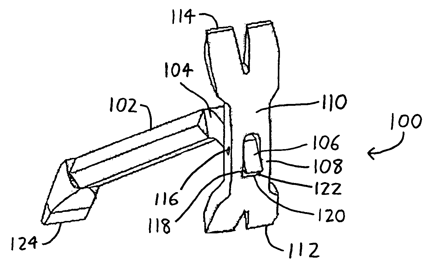
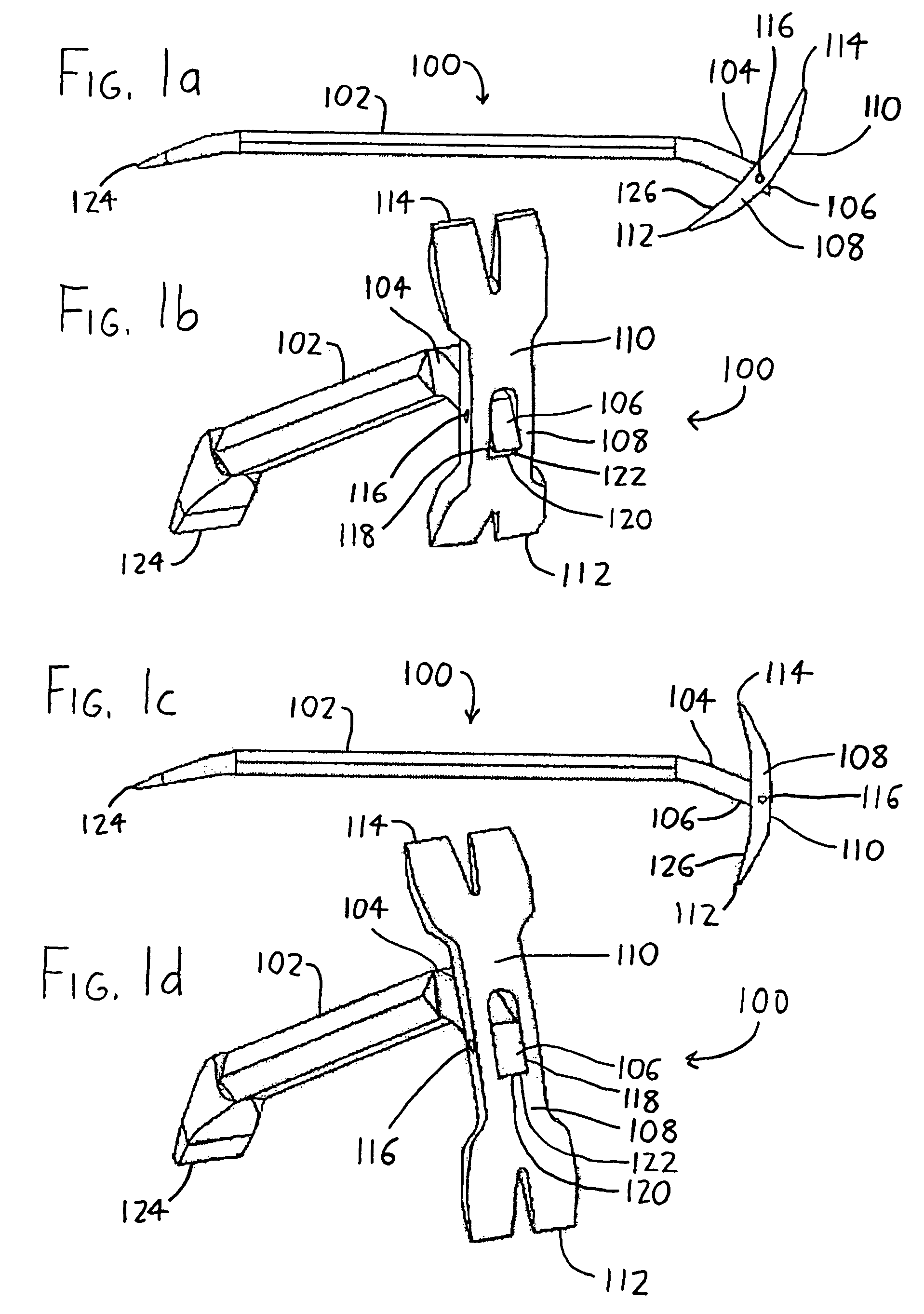
[0012]Referring initially to FIGS. 1a–1d (which are collectively referred to as FIG. 1), the pulling tool is presented in the form of a crowbar 100. The crowbar 100 has an elongated handle 102 with a tool head 104 at one end and a prying wedge 124 at its opposite end. The tool head 104 defines an anchor 106 against which a nail or other protrusion will be grasped, and it includes a jaw 108 which is pivotally affixed to the anchor 106 at pivot 116. The jaw 108 includes a jaw tip 112 and an opposing jaw tail 114, both of which are preferably defined as furcated prying wedges. A top bearing surface 110 curves in an arc from the jaw tip 112 to the jaw tail 114. An opposing jaw bottom surface 126 (FIGS. 1a and 1c), which faces the handle 102, also extends between the jaw tip 112 and the jaw tail 114. A cutout 118, defined as an aperture extending between the bearing surface 110 and the jaw bottom surface 126, is situated between the jaw tip 112 and the jaw tail 114. One side of the cutou...


PUM


Abstract

A pulling tool for pulling nails, screws, rivets, pegs, or other protrusions includes a jaw which may be opened to receive the head of the protrusion. The jaw is then at least partially closed against the protrusion, and when the handle of the tool is pulled, the jaw is both urged shut and also away from the surface from which the protrusion extends. Thus, as the protrusion is pulled, its shaft is also more tightly grasped, which helps to pull the protrusion from the surface without stripping off its head/cap. The pulling tool can be provided as a part of a hammer, crowbar, or other conventional tool.

Description

FIELD OF THE INVENTION[0001]This document concerns an invention relating generally to hand tools, and more specifically to hand tools which allow the pulling of nails or other small protrusions (screw or rivet heads, nuts, pegs, etc.) from the surfaces from which they protrude.BACKGROUND OF THE INVENTION[0002]Claw hammers are perhaps the best known tool for pulling nails from boards or other surfaces. The claw hammer has a curved top bearing surface which ends in a furcated tail or “claw” opposite the hammer head. When a nail is to be pulled, the nail head is situated between the furcations, and the top bearing surface is rolled along the board (or other surface from which the protrusion extends) in a tail-to-head direction so that the curvature of the bearing surface lifts the furcations (and thus the nail head) from the board. The problem with this arrangement is that the cap of the nail head—which bears against the furcations of the hammer tail, with the nail shaft resting in the...

Claims


Application Information

Patent Timeline
Patent Type & Authority Patents(United States)
IPC IPC(8): B66F15/00
CPCB25D1/04B25C11/00
Inventor EBY, ERIC H.PARDUHN, RICK
Owner BENEBY TOOL
Why Eureka
Try Eureka