Lens blind feature for motion detector

a motion detector and blind feature technology, applied in the field of passive infrared motion detectors, can solve the problems of not being able to adjust the detection angle to exclude the motion of the neighbor's yard from detection, not being able the fixed field of view may be too wide or too narrow to fully meet the needs of a particular user,

Active Publication Date: 2006-01-17
CORDELIA LIGHTING
View PDF8 Cites 29 Cited by
  • Summary
  • Abstract
  • Description
  • Claims
  • Application Information

AI Technical Summary

Benefits of technology

[0009]Certain embodiments of the invention may incorporate particular features. For example, a control panel having a blind adjustment knob located outside of the motion detector housing may be provided. The blind may be connected with the adjustment knob so that rotating the knob also rotates the blind. In certain embodiments, more than one blind may be employed. Each blind may optionally be interconnected with a separate adjustment knob so as to be independently movable.

Problems solved by technology

However, the fixed field of view may be too wide or too narrow to fully meet a particular user's needs.
The user is not able to adjust the detection angle to exclude motion in the neighbor's yard from detection.
This arrangement does not, however, allow the user to change the detection angle.
Another known approach is to glue a piece of tape across a portion of the aperture through which signals pass, thereby limiting the angle of detection.
However, both approaches are unsightly, somewhat cumbersome to implement, and cannot withstand the effects of weather if the lamp and detector are used outdoors.

Method used


Image

  • Lens blind feature for motion detector
  • Lens blind feature for motion detector
  • Lens blind feature for motion detector

Examples


Embodiment Construction

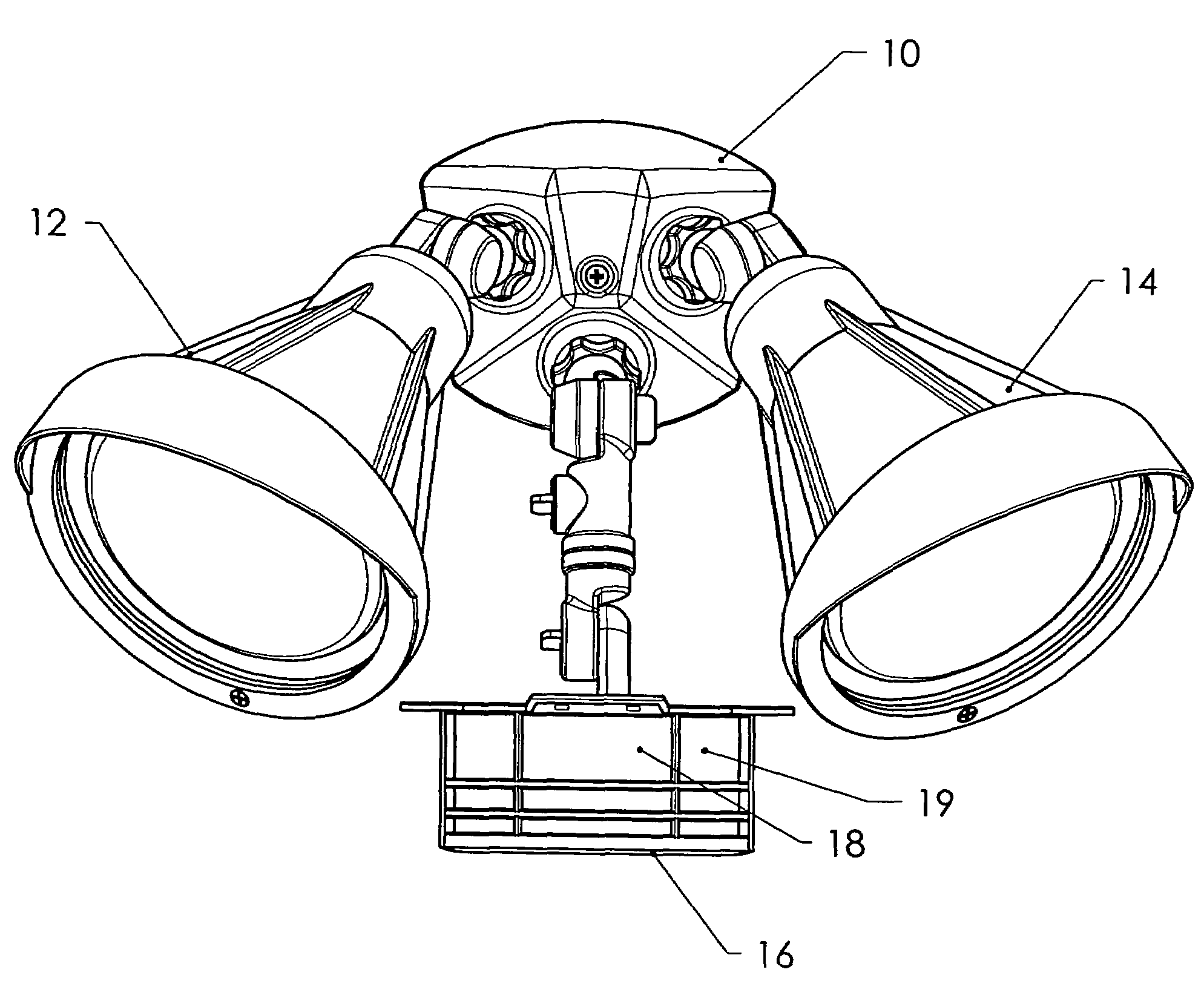
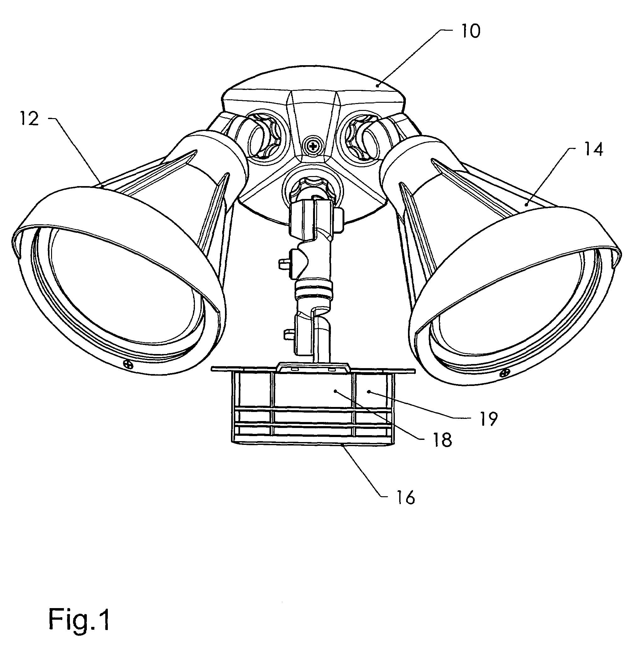
[0020]The present invention is directed to a light fixture having a motion detector incorporated therein, wherein the motion detector includes one or more adjustable internal blinders that limit the signals reaching motion detector. FIG. 1 illustrates one embodiment of the present invention. Specifically, FIG. 1 is a front elevational view of a dual flood light assembly 10 having flood lights 12 and 14, and a housing 16 in which motion detection circuitry resides. The housing 16 in the exemplary embodiment is separate and discrete from the lights 12, 14. On the other hand, in various alternative embodiments, the motion detector housing may be incorporated into the lamp housing in a one-piece or integrated design.

[0021]The housing 16 includes an aperture or window 18 through which infrared radiation may pass. An optional lens 19 covers the window 18. The lens 19 may be a Fresnel type or may be a plain sheet of translucent or transparent polymer. The lens 19 is preferable designed to ...


PUM


Abstract

A light fixture has motion detection circuitry enclosed within a motion detector housing. The motion detector housing contains at least one thermal detector such as a passive infrared sensor, the sensor having a detection angle. At least one adjustable blind is housed within the housing adjacent to the infrared sensor, and the blind is adjustable to block and limit the detection angle of the sensor. The blind may be directly connected to a knob on a control panel that allows the user to alter the angle of the blind. Two or more blinds may be used on the interior of the housing, to increase adjustability of the detection angle.

Description

BACKGROUND OF THE INVENTION[0001]The present invention relates to passive infrared motion detectors of the type used in residential outdoor lighting fixtures. The lighting fixtures may, for example, illuminate a walkway or driveway when a person or automobile approaches. The invention is more particularly directed to arrangements for limiting the detection angle of the motion detectors.[0002]Lighting fixtures that automatically turn on a light when a person or a motor vehicle approaches have been known for some time. A popular form of such a lighting fixture includes a device that is responsive to infrared radiation emitted by a person or motor vehicle as the person or vehicle moves within the field of view of the device. These devices are generally referred to as passive infrared, or “PIR,” motion detectors. These detectors are incorporated into the lighting fixture housing to trigger the lamp upon detection of the person, motor vehicle, or like heat emitting object.[0003]PIR motio...

Claims


Application Information

Patent Timeline
Patent Type & Authority Patents(United States)
IPC IPC(8): G01J5/02
CPCG01J5/04G01J5/08G01J5/0831G01J5/089H05B37/0227G01J5/0843Y02B20/44H05B47/115H05B47/13Y02B20/40G01J5/07
Inventor MONROE, TIMCHAN, PETER
Owner CORDELIA LIGHTING
Why Eureka
Try Eureka