Method for fringe field compensation of an actively shielded superconducting NMR magnet

a superconducting magnet and active shielding technology, applied in the direction of superconducting magnets/coils, using reradiation, magnetic materials, etc., can solve the problems of deterioration of fringe field compensation and insufficient utilization of possible fringe field reduction of magnets, so as to facilitate the compensation method, increase the accuracy of dipole moment compensation, and flexible magnet coil arrangement

Inactive Publication Date: 2006-01-17
BRUKER BIOSPIN
View PDF7 Cites 6 Cited by
  • Summary
  • Abstract
  • Description
  • Claims
  • Application Information

AI Technical Summary

Benefits of technology

[0023]The basic idea of the invention is to subdivide the main magnet, i.e. the main coil of the magnet coil arrangement into at least one first and one second partial region. If the same current flows through all partial regions of the main magnet, the main magnet has an uncompensated additional dipole moment, which is associated with an undesired excessive fringe field, e.g. at the specified location of the 5-Gauss line, e.g. due to production tolerances. This excessive fringe field is initially determined through measurements (for later charging of the same magnet coil arrangement, determination of the fringe field profile of the uncompensated magnet coil arrangement must not be repeated). The two partial regions have opposite influences on this fringe field. Due to the inventive method, a non-vanishing current difference of ΔI(2)−ΔI(1) between the two partial regions is set at the end of the charging process, to reduce the magnetic fringe field and adjust the specified fringe field distribution of the magnet coil arrangement. This permits compensation of the excessive fringe fields which occur due to production tolerances. The inventive method requires only one power supply unit for charging the entire magnet coil arrangement, which reduces the costs of the magnet coil arrangement.
[0039]In a further sub-variant of the above-mentioned method variant, the first partial region effects rough compensation and the third partial region effects fine compensation of the dipole moment. The fringe field is measured between closings of the additional switches. Subdivision of compensation into rough and fine adjustment improves the overall accuracy of the dipole compensation which can be obtained.

Problems solved by technology

Direct influence, in that the field portions of the shielding magnet region and of the residual magnet do not correspond to the optimum theoretical values due to tolerances, which results in deterioration of the fringe field compensation.
This procedure is, of course, greatly disadvantageous in that the theoretically possible fringe field reduction of the magnet is not utilized.

Method used


Image

  • Method for fringe field compensation of an actively shielded superconducting NMR magnet
  • Method for fringe field compensation of an actively shielded superconducting NMR magnet
  • Method for fringe field compensation of an actively shielded superconducting NMR magnet

Examples


case 1

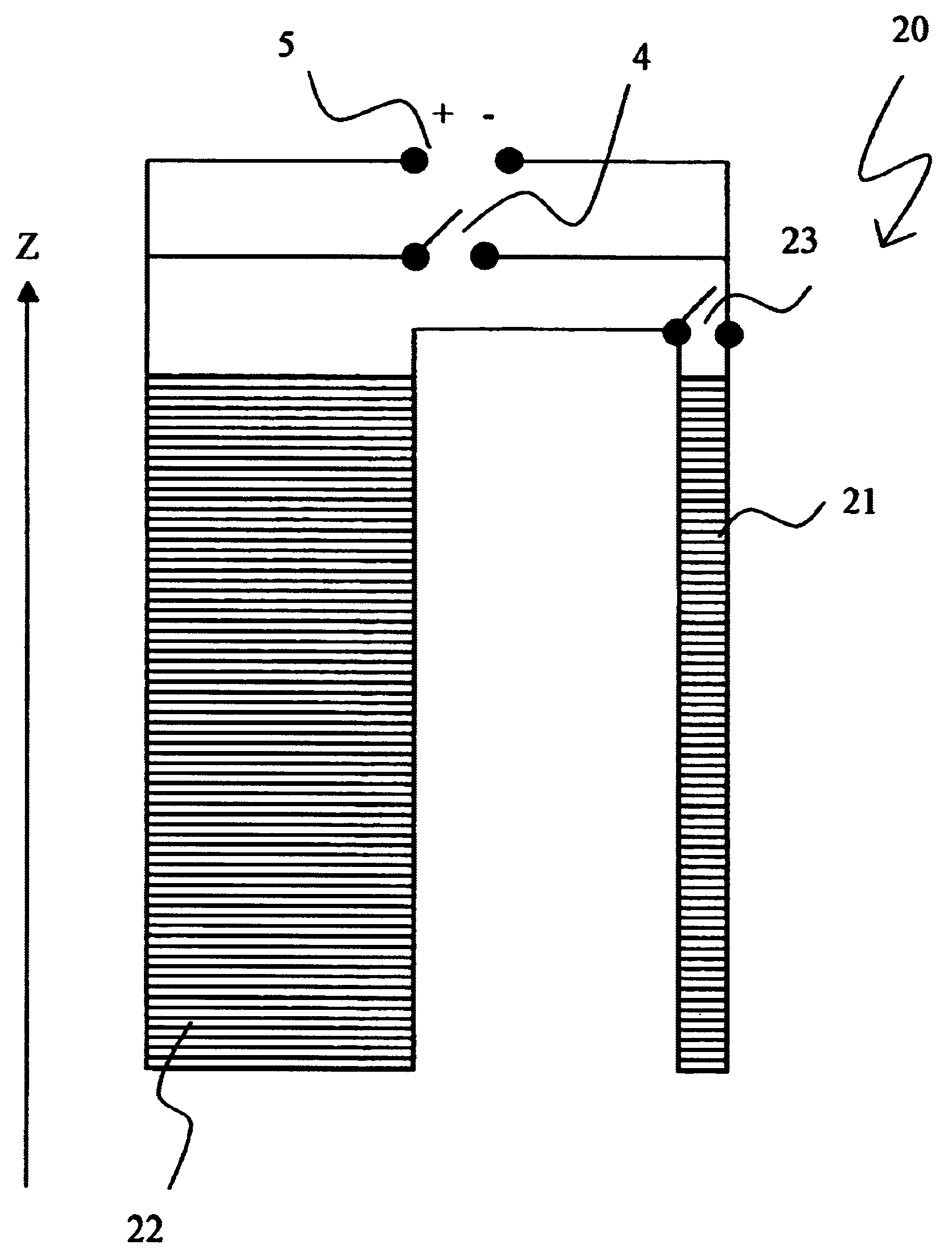
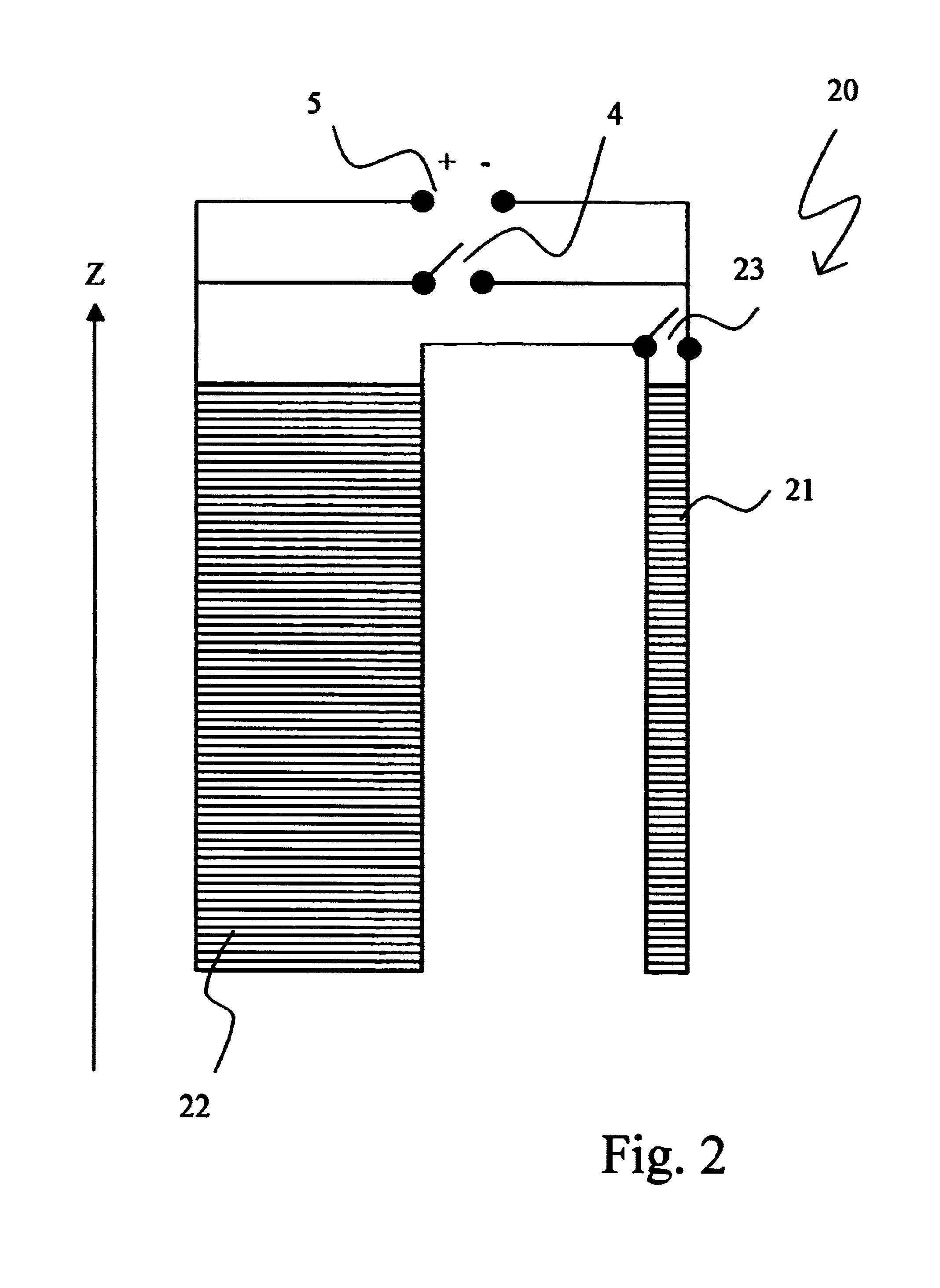
[0060] the additional dipole moment of the overall system which is caused by production tolerances and which is determined from the fringe field measurement, is positive. If the first partial region 21 (shielding portion) is short-circuited at the right time and the magnet coil arrangement 20 is further charged, an additional current is induced in the short-circuited first partial region 21 which increases its negative dipole moment to such an extent that, when the end field B has been reached, the additional dipole moment caused by production tolerances is eliminated in cooperation with the direct influence of the second partial region 22 on the dipole moment.

case 2

[0061] the additional dipole moment of the overall system which is caused by production tolerances and is determined from the fringe field measurement is negative. In this case, the target field B must be swept and the first partial region 21 must then be short-circuited. If the remaining magnetic coil arrangement 20 is discharged, an additional current is induced in the short-circuited first partial region 21 which reduces the negative dipole moment in this partial region to such an extent that the additional dipole moment caused by production tolerances is eliminated in cooperation with the direct influence of the second partial region 22 on the dipole moment after the end field B has been reached.

[0062]If, during subdivision of the partial regions, the first partial region which consists of the shielding portion, is also associated with a region of the main field portion, the inductive coupling between these two partial regions may also become positive. In this case, the above-de...


PUM

PropertyMeasurementUnit
magnetic fieldsaaaaaaaaaa
magnetic dipole momentsaaaaaaaaaa
current strengthaaaaaaaaaa

Abstract

The invention concerns a method for charging an actively shielded magnet coil arrangement (20) comprising a first partial region (21) which can be superconductingly short-circuited using an additional switch (23), and a second partial region (22), wherein the two partial regions (21, 22) generate dipole moments of different signs. The magnetic fringe field B* is measured close to the desired operating state of the arrangement (20) and operating currents are determined for each of the two partial regions (21, 22) at which the overall magnetic field B is free from an additional dipole moment caused by production tolerances to permit setting of the theoretically optimum fringe field, irrespective of production tolerances. These operating currents are adjusted taking into consideration the inductive coupling between the partial regions (21, 22) through initially charging the entire magnet coil arrangement (20) and, after closing the additional switch (23), through continuation of the charging process in the second partial region (22) only. This eliminates deviations, which are caused by production tolerances, from the optimum theoretical fringe field of the arrangement (20) in a simple and inexpensive manner.

Description

[0001]This application claims Paris Convention priority of DE 103 44 983.3 filed Sep. 27, 2003 the complete disclosure of which is hereby incorporated by reference.BACKGROUND OF THE INVENTION[0002]The invention concerns a method for charging an actively shielded magnet coil arrangement, which is superconductingly short-circuited during operation via a superconducting main switch, in particular, of an NMR magnet, wherein the magnet coil arrangement comprises at least one first and one second partial region, wherein at least the first partial region can be separately short-circuited via an additional superconducting switch, and wherein the two partial regions generate magnetic fields during operation whose magnetic dipole moments D(1) and D(2) have opposite signs.[0003]Actively shielded magnets have a considerably reduced magnetic fringe field outside of the magnet coil arrangement, i.e. the field strength decreases rapidly with increasing separation from the magnetic center of the ma...

Claims


Application Information

Patent Timeline
Patent Type & Authority Patents(United States)
IPC IPC(8): G01R33/421G01R33/3815H01F6/00
CPCH01F6/006G01R33/3815G01R33/421
Inventor FRANTZ, WOLFGANG
Owner BRUKER BIOSPIN
Why Eureka
Try Eureka