Ground arrangement for a device using wireless data transfer

a wireless data transfer and ground arrangement technology, applied in the direction of antenna earthings, antenna supports/mountings, antennas, etc., can solve the problems of affecting the operation of components, affecting the normal functioning of the device, interfering signals, etc., and achieves cost-effectiveness, easy implementation, and increased effective length of ground leads

Inactive Publication Date: 2006-01-17
FLEXTRONICS SALES & MARKETING A P
View PDF16 Cites 19 Cited by
  • Summary
  • Abstract
  • Description
  • Claims
  • Application Information

AI Technical Summary

Benefits of technology

[0009]The objective of the invention is to achieve a solution for a wireless terminal device by means of which it is possible to simply and flexibly optimize the electric properties of the device antenna, the performance of the device as well as to minimize the SAR value to be measured from the device.
[0012]The solution in accordance with the invention is used to achieve not only a small SAR value but also a low-loss antenna structure that has a VSWR value (VSWR=Voltage Standing Wave Ratio) as small as possible. By means of the invention it is also possible to achieve an antenna structure that operates in each situation with an optimal amplification.
[0014]In another advantageous implementation mode of the invention, the additional ground leads are disposed in different layers of a multi-layer PC board. In this manner it is possible easily to implement additional ground leads that possess even very different sizes and shapes. The additional ground leads are easy to implement in respect of manufacturing technique on a multi-layer PC board, which makes the solution also cost-effective.
[0015]Since the effective length of the ground leads can be increased when necessary, it enables one to easily implement various ground configurations, from which the one each time most suitable is chosen. In practice, especially the frequency band to be used has an effect on the selection of the ground configuration (i.e. the additional ground lead each time most suitable).
[0016]The ground configuration in accordance with the invention can be easily implemented, and the user does not have to do anything in order to introduce a new ground configuration, but the introduction is performed automatically based on predetermined criteria.

Problems solved by technology

In practice, interfering signals are received into the antenna, which render difficult the normal functioning of the device, at least to some extent.
The devices in use themselves cause interfering signals that may e.g. harm the operation of the components in the device.
The aforementioned solution is therefore cumbersome in use.

Method used


Image

  • Ground arrangement for a device using wireless data transfer
  • Ground arrangement for a device using wireless data transfer
  • Ground arrangement for a device using wireless data transfer

Examples


Embodiment Construction

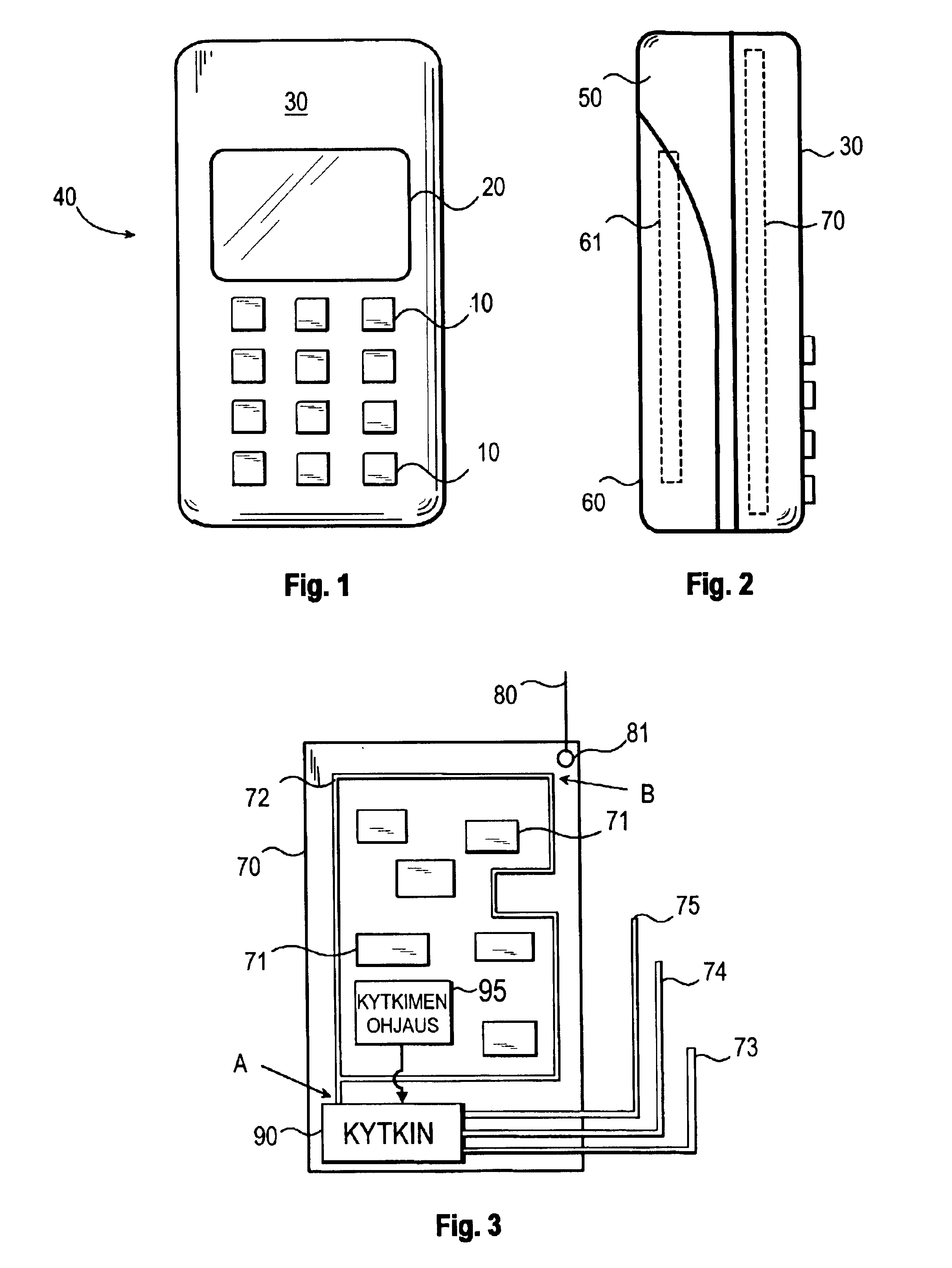
[0026]FIG. 1 shows a front view of a typical (subscriber) terminal device. The terminal device may be e.g. a mobile phone 40, which comprises, among other things, keys 10 and a display 20. The terminal device may also be some other device than a mobile phone, since from the standpoint of the invention substantial is only the fact that the device is capable of sending and receiving via an air interface.

[0027]The terminal device of FIG. 1 comprises a cover or enclosure structure, of which in the figure can be seen the front cover, i.e. the so-called A cover 30. The cover structure can be made e.g. of plastic, glass fiber or metal or a combination thereof.

[0028]FIG. 2 shows a side view of the terminal device, which allows the cover structure of the terminal device to be better seen. In addition to the front cover, the terminal device comprises a rear cover, i.e. a so-called B cover, and an accumulator space 61 for the accumulator. The proposed terminal device comprises, in addition, an...


PUM


Abstract

The invention relates to a ground arrangement of a device using wireless data transfer. In order to improve the electric properties of the device and to minimize the SAR value of the device, at least one electrically conductive additional ground lead (73-75) is formed in the device in addition to the actual ground lead (72). In between the ground lead and the additional ground lead, a galvanic coupling is automatically established, when a predetermined switching criterion is fulfilled, and the aforementioned galvanic coupling is automatically released, when a predetermined release criterion is fulfilled. This enables one to change the ground configuration of an antenna such that it is as suitable as possible for the transmission and reception circumstances each time existing.

Description

TECHNICAL FIELD OF THE INVENTION[0001]The invention relates to the ground arrangement of a device using wireless data transfer, such as a mobile phone. By means of ground arrangement one tries to improve the electric properties of the device antenna as well as the performance of the device.BACKGROUND OF THE INVENTION[0002]Wireless terminal devices such as mobile phones must meet various requirements. As the physical size of the devices gets smaller, their size imposes their own requirements e.g. on the device structure, and particularly on the ground structure of the device. The antenna is a very important part of a terminal device operating at high frequencies, since it converts the signal received from the transmitter into electromagnetic waves and the electromagnetic waves into the signal to be received.[0003]The antenna has to be capable of receiving and sending signal as well as possible under all circumstances. The frequency and output of a signal passing through the antenna m...

Claims


Application Information

Patent Timeline
Patent Type & Authority Patents(United States)
IPC IPC(8): H01Q1/24H01Q9/16H01Q1/52
CPCH01Q1/526H01Q1/245H01Q1/48
Inventor KURJENHEIMO, TIMORAISANEN, KARI
Owner FLEXTRONICS SALES & MARKETING A P
Why Eureka
Try Eureka