Elevator door monitoring system

a technology for monitoring systems and elevators, applied in elevators, transportation and packaging, building lifts, etc., can solve the problems of reducing the voltage in the safety circuit, the length of the connection, and the relatively high assembly cost of individual safety contacts, so as to achieve the effect of reducing the risk of failur

Inactive Publication Date: 2006-01-24
INVENTIO AG
View PDF12 Cites 31 Cited by
  • Summary
  • Abstract
  • Description
  • Claims
  • Application Information

AI Technical Summary

Benefits of technology

[0013]The foregoing and other objects are met by a monitoring system in accordance with the invention for a lift system in which the shaft doors and / or the cage doors have sensor means by which their state, i.e. the adoption of their open setting or closed setting, is detected. The monitoring system further comprises an evaluating system which is connected with the sensor means and which evaluates the signals delivered by the sensor means. This evaluation is carried out at short intervals in time and makes it possible to detect the state of the monitored shaft door or cage door; similarly, changes of the signal characteristic over time are detected.
[0015]In contrast to a system with a safety circuit, it is not only possible to establish that a fault has occurred, but the evaluating unit can also localize a fault from the signals of the sensor means and thus an analysis and diagnosis relating to the fault is possible. In addition, through the evaluation of the signal characteristics of the signals delivered by the sensor means, diminutions in quality over time can be detected so that precautionary maintenance measures can be initiated.
[0021]It is of greatest advantage if the evaluating system is so conceived that it also detects the changes in signal characteristics over time, i.e. the characteristics of the signals to be evaluated; abnormal bounce behaviour of sensor means or abnormal dynamic signal courses and / or abnormal static states, for example a voltage drop, at a sensor means can thereby be detected. It is thus possible to carry out diagnoses at the level of individual components and to arrange advance maintenance of individual sensors.

Problems solved by technology

Monitoring systems with safety circuits of this kind are subject to numerous disadvantages, which are briefly listed in the following:Each safety circuit has inherent problems; including the length of the connections, the voltage drop in the safety circuit and the relatively high assembly cost.The individual safety contacts are comparatively susceptible to failure; unnecessary emergency stops of the lift system therefore frequently occur.Notwithstanding a monitoring system with a safety circuit, unsafe or risky situations cannot be avoided; on the one hand the safety contacts individually or in common can be relatively easily bridged over, which is virtually equivalent to the absence of safety precautions, and on the other hand, while an open shaft door does indeed prevent movement of the cage, if the cage is not disposed at the then open shaft door the risk still exists of a fall through the open shaft door.Intelligent or situation-appropriate reactions, for example in the case of an open safety circuit, are not possible; in particular, it cannot be avoided that persons are unintentionally trapped in the lift cage.The monitoring system does not permit a specific diagnosis, i.e. in the case of an open safety circuit it can only be established that at least one safety contact and thus one lock or at least one shaft door is open.
It cannot be established, however, which safety contact or contacts is or are open.A precautionary maintenance is not possible, since there are no indications about the state of the safety contacts; it is thus not possible to service the lift system in advance and to replace worn safety contacts in good time, and at a point in time in which the lift system can be shut down without problems, except within the scope of a periodic inspection wherein, however, in many cases taking the lift system out of operation, which is not necessary as such, is carried out.The availability of the lift is restricted, since an open safety contact always has the consequence of taking the lift system out of operation even if another solution, for example blocking the access region to a non-closable shaft door, would be possible.

Method used


Image

  • Elevator door monitoring system
  • Elevator door monitoring system

Examples


Embodiment Construction

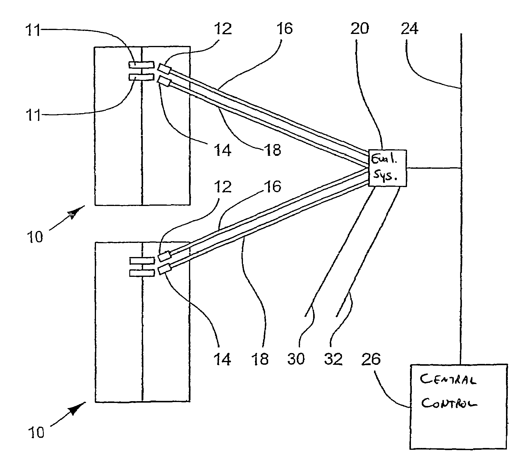
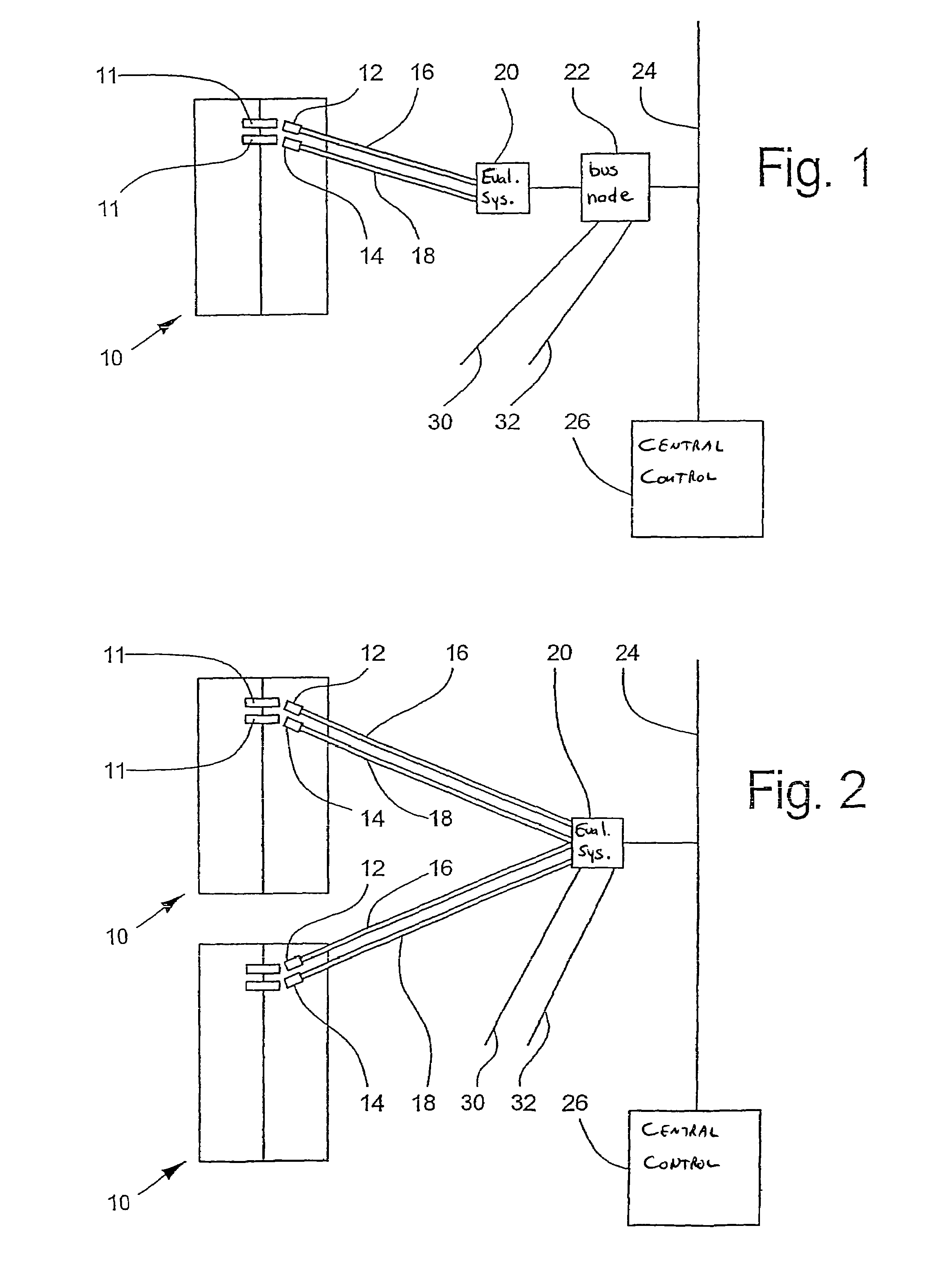
[0029]FIG. 1 shows an arrangement with decentralized evaluation. A lift system, which is not illustrated in more detail, comprises a door 10, which can be a shaft door or a cage door. Sensor means, namely a first sensor means 12 and a second sensor means 14, are associated with the door 10. Each of the sensor means12, 14 has one or more sensors (not shown) which, in the present example of embodiment, are constructed as switches and are actuable by way of door elements 11. The sensor means 12, 14 are connected by way of connections 16, 18 to an evaluating system 20 which is intended only for the evaluation of the signals of the door 10. The evaluating system 20 is connected by way of a bus node 22 to a data bus 24, which is connected to a central control 26. In addition to the signals delivered by the sensor means 12, 14, other signals, i.e. other lift magnitudes, are connected to the bus node 22 by way of further connections 30, 32; in addition, a connection to the evaluating system...


PUM


Abstract

A monitoring system for monitoring doors such as a shaft or cabin door, of a lift installation includes a sensor element associated with the doors for monitoring the state or position of the door. An evaluation system is connected to the sensor element and evaluates the sensor signals. The evaluation system can perform continued evaluation in short time intervals in order to provide a continuous record of the state of the monitored doors and temporal changes in the signal characteristics of the sensor signals.

Description

[0001]The invention relates to a monitoring system for monitoring a shaft door or cage door of a lift system. The present application is a continuation of PCT / CH02 / 00499 filed Sep. 11, 2002.BACKGROUND OF THE INVENTION[0002]Lift systems these days comprise so-termed double doors, i.e. not only shaft doors, but also cage doors arranged at the lift cage. The opening and closing of the shaft doors is usually carried out by the cage or the cage doors. For reasons of safety, during lift operation all shaft doors must always be closed, with the exception of the shaft door of that story at which the lift cage has just stopped. Similarly, the cage doors must be closed when the lift is not stopped at a story in order to be loaded or unloaded or to be entered or left. For maintenance reasons the shaft doors and / or cage doors can obviously also be opened when the lift cage is located otherwise than in the above-described positions. The state, i.e. the setting, of the shaft doors and cage doors,...

Claims


Application Information

Patent Timeline
Patent Type & Authority Patents(United States)
IPC IPC(8): B66B1/34B66B5/00B66B13/14B66B13/22
CPCB66B5/0031B66B13/22
Inventor DEPLAZES, ROMEOANGST, PHILIPP
Owner INVENTIO AG
Why Eureka
Try Eureka