Mounting member with snap in swivel member

a technology of mounting member and swivel member, which is applied in the direction of washstands, scaffold accessories, light support devices, etc., can solve the problems of loosing of both the gripper and the support post, and achieve the effect of reducing the manufacturing and assembly process of the bracket or block

Inactive Publication Date: 2006-01-24
DELAWARE CAPITAL FORMATION INC
View PDF129 Cites 40 Cited by
  • Summary
  • Abstract
  • Description
  • Claims
  • Application Information

AI Technical Summary

Benefits of technology

[0012]Therefore, the present invention provides a snap in swivel member suitable for use with a unitary gripper or workpiece holder mounting bracket or a rear mounting block for a workpiece holder or other types of mounting brackets or mounting blocks. The swivel member may allow for pivotable and rotational adjustment of the mounting bracket or block or the like with respect to a generally fixed support structure or rod or post or the like. Adjustment of the support structure or post and / or the swivel member within the opening in the mounting bracket or block may be performed via adjustment of a single fastener. The lateral dimensions of the unitary bracket of the present invention, and thus the material required to make the bracket, may be reduced over the prior art, since each fastener is positioned generally adjacent to the respective opening in the bracket and does not extend laterally outwardly of an outermost diameter of the bracket at which the bracket engages and retains the gripper assembly. Because the bracket or mounting block of the present invention may be a unitarily formed bracket or block, manufacturing and assembly processes of the bracket or block may be reduced.

Problems solved by technology

However, loosening of the fastener results in loosening of both the gripper and the support post.

Method used


Image

  • Mounting member with snap in swivel member
  • Mounting member with snap in swivel member
  • Mounting member with snap in swivel member

Examples


Embodiment Construction

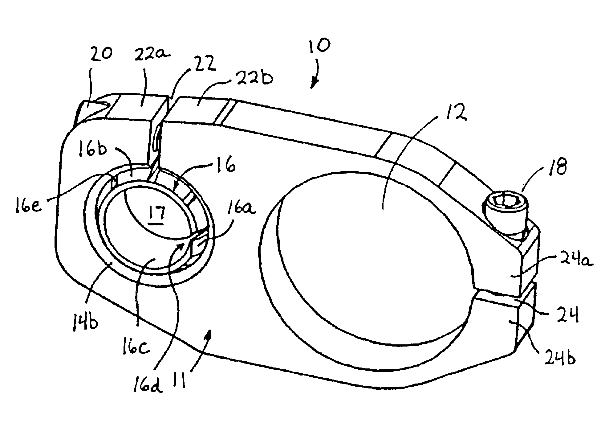
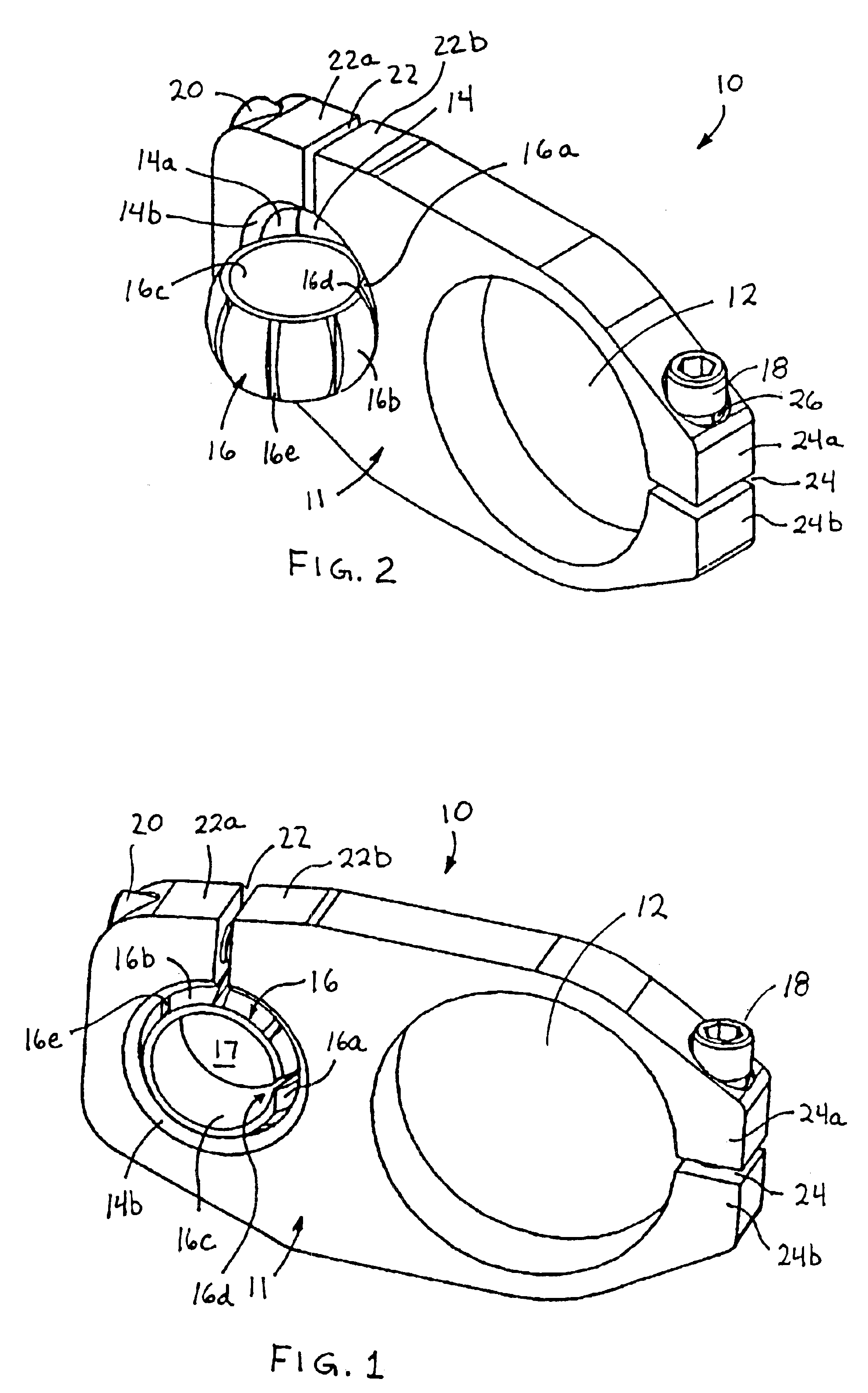
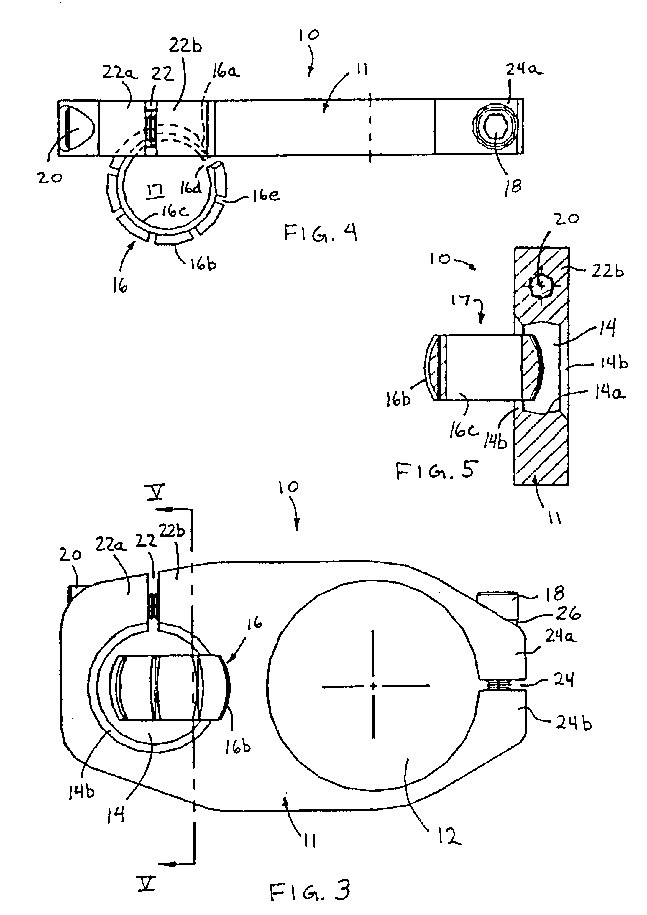
[0022]Referring now to the drawings and the illustrative embodiments depicted therein, a gripper or workpiece holder mounting bracket assembly 10 is adapted to mount a workpiece holder (not shown), such as a gripper or other holder or tool or the like, to a support structure (also not shown), such as a generally cylindrical rod or post, or other elongated, generally cylindrical support member (FIGS. 1 and 2). Mounting bracket assembly 10 includes a unitary bracket member 11, which defines a generally circular opening 12, which may pivotally receive the workpiece holder. Bracket member 11 also defines a second, generally circular opening 14 (FIGS. 2, 3 and 5) for adjustably receiving a donut swivel or swivel member or ring 16, which may receive the support structure or rod therethrough. A fastener 18 is provided at the opening 12 and may be adjustable to adjust a clamping force at opening 12, while a second fastener 20 is provided at opening 14 to adjust a clamping force at opening 1...


PUM


Abstract

A mounting assembly for pivotally mounting a workpiece holder to a support structure includes a mounting member having an opening at least partially therethrough and a swivel member. The swivel member has a generally cylindrical passageway therethrough for at least partially receiving a support structure. The swivel member defines a truncated, generally spherical shaped swivel member having a curved outer surface for engaging an inner surface of the opening of the mounting member. The swivel member includes a reduced diameter or chamfered portion at the outer surface to facilitate insertion of the swivel member into the opening of the mounting member, whereby the swivel member is substantially retained within the opening after insertion therein. The mounting member may be a mounting bracket for adjustably mounting to a workpiece holder or may be a mounting block which is attachable to a workpiece holder.

Description

FIELD OF THE INVENTION[0001]The present invention relates generally to mounting members or brackets for a gripper or other workpiece holder and, more particularly, to a mounting member or bracket which may receive or attach to a gripper or workpiece holder and which is adjustably mountable to a rod or support structure.BACKGROUND OF THE INVENTION[0002]Mounting brackets or blocks for mounting a gripper or workpiece holder or the like to a support structure are well known in the art. The mounting brackets engage a cylindrical portion of the gripper and mount to a cylindrical support rod or arm. Some mounting blocks or the like may attach to a portion of the gripper, such as a rear plate or portion of the gripper. Such grippers or workpiece holders are typically implemented at assembly lines or other industrial applications and connected to support structures along the assembly line or machines.[0003]In order to provide pivotable adjustment of the gripper relative to the bracket, while...

Claims


Application Information

Patent Timeline
Patent Type & Authority Patents(United States)
IPC IPC(8): F21V35/00B25B5/14F16C11/06F16C11/10F16M11/14F16M13/02
CPCB25B5/147F16C11/0614F16C11/106F16M13/02F16M11/14F16M2200/024F16M2200/022
Inventor ATTEE, KEITH S.
Owner DELAWARE CAPITAL FORMATION INC
Why Eureka
Try Eureka