
Spacer profiles for double glazings

a technology for spacer profiles and double glazing, applied in the field of spacer profiles, to achieve the effect of improving spacer profiles

Active Publication Date: 2006-01-24
TECHNOFORM GLASS INSULATION HLDG
View PDF42 Cites 74 Cited by
  • Summary
  • Abstract
  • Description
  • Claims
  • Application Information

AI Technical Summary

Benefits of technology

The solution provides improved heat insulation, minimizes water condensation, and maintains structural integrity during bending, ensuring effective performance in insulating window units even at low temperatures.

Problems solved by technology

Further, insulating window units may be prepared by placing the bent spacer frame between two window panes in a manner and position that permits a limited range of relative movement by the window panes when the assembled insulating window unit is subjected to pressure changes and / or shearing strain.

Method used


Image

  • Spacer profiles for double glazings
  • Spacer profiles for double glazings
  • Spacer profiles for double glazings

Examples


Embodiment Construction

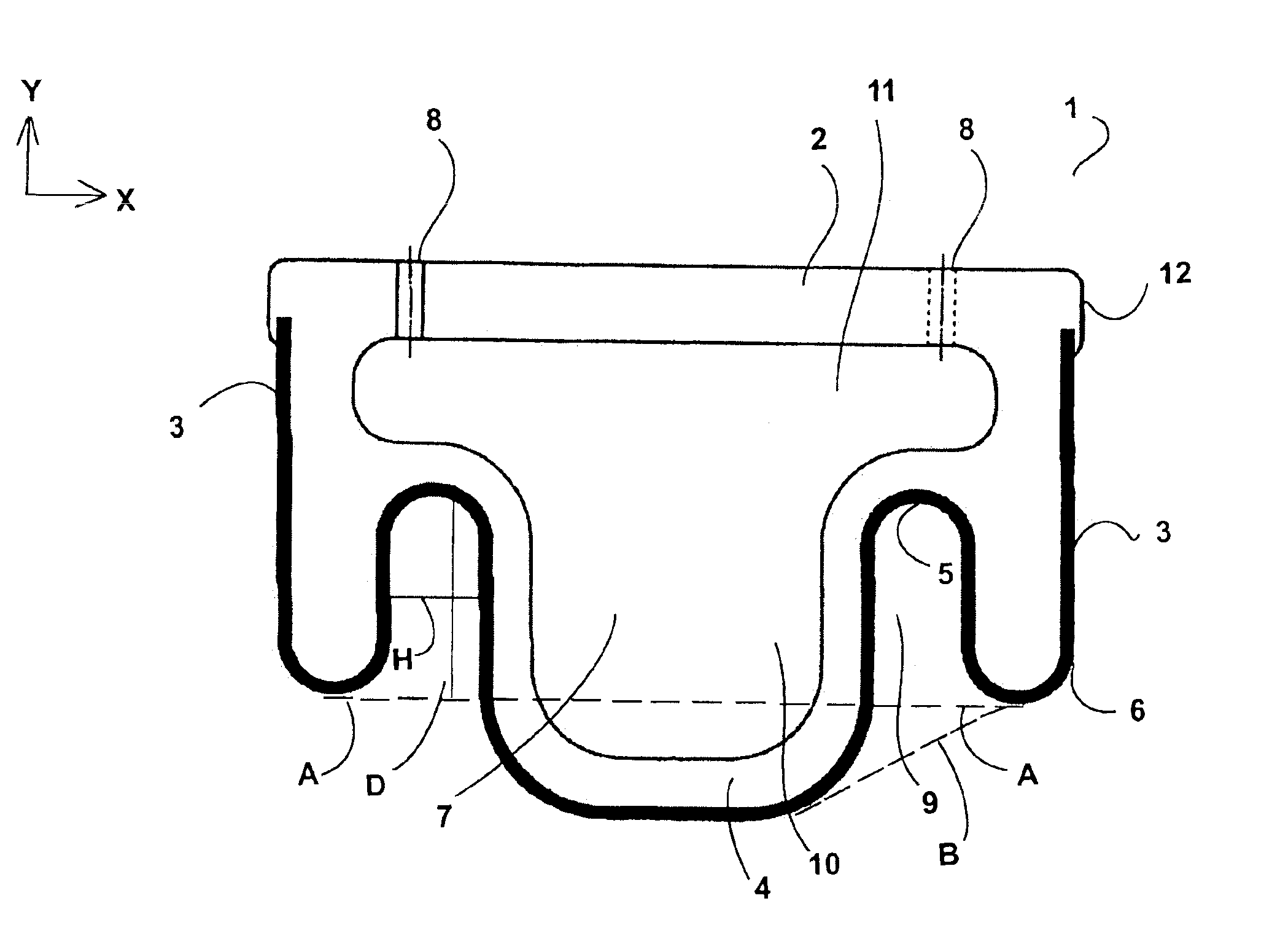
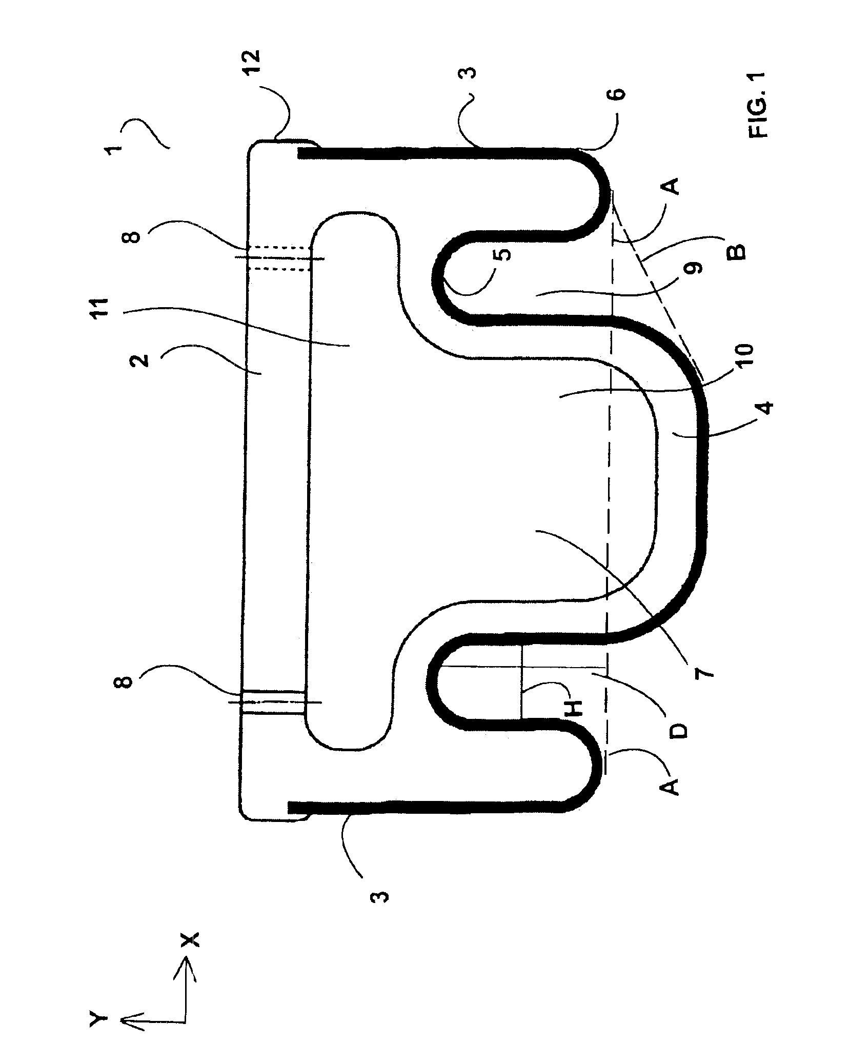
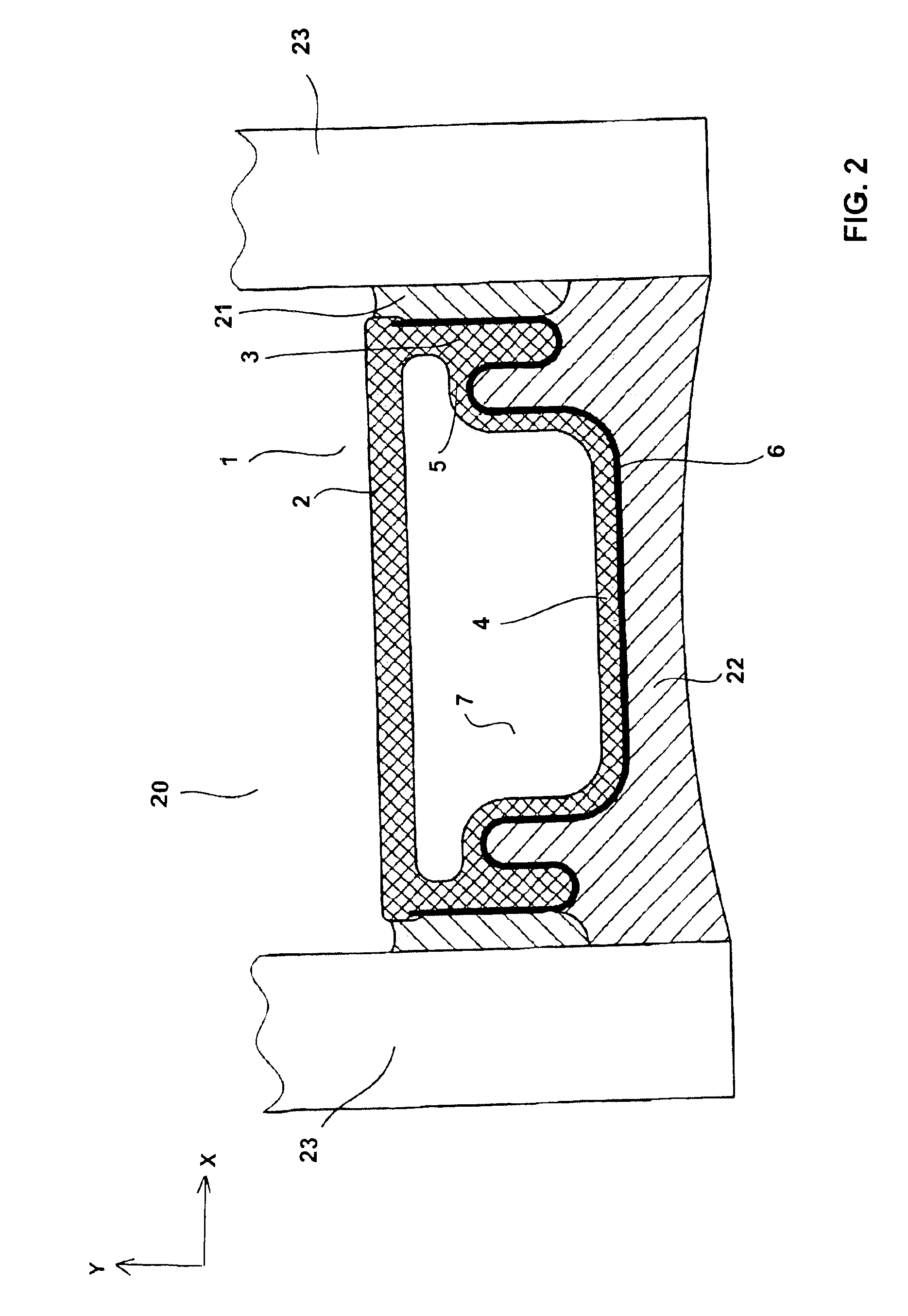
[0028]In one embodiment of the present teachings, spacer profiles may include a profile body having a base wall, first and second side walls extending from the base wall, and an upper wall extending substantially in parallel with the base wall. A first connecting segment preferably connects the first side wall to the upper wall and a second connecting segment preferably connects the second side wall to the upper wall. The first and second connecting segments respectively may define an inwardly curved or angled (e.g., substantially V-shaped or U-shaped) groove (or recess) between the upper wall and the respective first and second side walls. In addition, the profile body preferably is formed as a single, integral, continuous piece without borders (interfaces) between the various components thereof (i.e., no interfaces between the upper wall, side walls, base wall, and connecting segments). In addition, the profile body preferably comprises an elastically-plastically deformable materi...


PUM

PropertyMeasurementUnit
breaking elongationaaaaaaaaaa
thicknessaaaaaaaaaa
thicknessaaaaaaaaaa

Abstract

Spacer profiles (1) for double glazing units (20) may include a deformable profile body having first and second side walls (3) extending from a base wall (2). First and second connecting segments (5) respectively connect the first and second side walls (3) to an upper wall (4) and respectively define inwardly projecting grooves (9). A hollow chamber (7) may include a first space (11) disposed adjacent to the base wall (2), which first space (11) has a greater width than a second space (10) disposed adjacent to the upper wall (4). Further, the profile body preferably has a heat conductivity of less than about 0.3 W / (m·K). A reinforcement layer (6) may be permanently coupled to at least the upper wall (4), the first and second connecting segments (5), and the first and second side walls (3), and preferably has a heat conductivity of less than about 50 W / (m·K).

Description

CROSS-REFERENCE[0001]This application claims priority to U.S. provisional patent application No. 60 / 518,215, which was filed Nov. 7, 2003, the contents of which are incorporated by reference as if fully set forth herein.TECHNICAL FIELD[0002]The present invention relates to spacer profiles that can be formed (e.g., bent) into spacer frames for mounting within an insulating window unit (double glazing). The spacer profiles are designed to support and separate two window panes.DESCRIPTION OF THE RELATED ART[0003]Known spacer profiles are taught by commonly-owned U.S. Pat. Nos. 6,035,596, 6,389,779 and 6,339,909. Additional spacer profiles are taught by U.S. Pat. Nos. 5,460,862, 5,962,090, 6,061,994, 6,192,652 and 6,537,629, PCT Publication Nos. WO 03 / 74830 and WO 03 / 74831, European Patent Publication No. 0 003 715 and German Patent Publication No. 33 02 659.[0004]Known insulating window units utilize two or more glass panes. The spacer profile is placed between two glass panes in order...

Claims


Application Information

Patent Timeline
Patent Type & Authority Patents(United States)
IPC IPC(8): B32B3/20E04C2/54E06B3/24E06B3/663
CPCE06B3/66319E06B2003/6638Y10T428/24744Y10T428/139E06B2003/6639
Inventor BRUNNHOFER, ERWINLENZ, JORG
Owner TECHNOFORM GLASS INSULATION HLDG
Learn More